Since its launch in 2014, ESP8266 has revolutionized the IoT space by offering an extremely cost-effective and programmable WiFi-enabled microcontroller to hobbyists and professionals, thereby opening the doors to all kinds of everyday objects and sensors to the internet. In addition, with it’s built-in WiFi capability, the ESP8266 can also serve as a standalone web server on a local network, and can respond to the http GET commands received from an internet browser. This project illustrates how to construct a simple standalone weather web server utilizing NodeMCU development board for ESP8266 and Bosch’s BME280 environmental sensor chip. On receiving the web requests, the ESP8266 responds back by returning back an HTML webpage containing the ambient temperature, humidity and pressure measurements. The webpage is refreshed automatically every 15 seconds to get the latest environmental data.
![Weather web server using ESP8266 and BME280 environmental sensor]()
Weather web server using ESP8266 and BME280 environmental sensor
Hardware
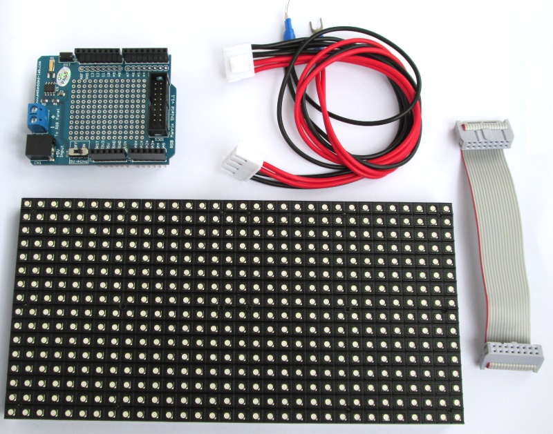
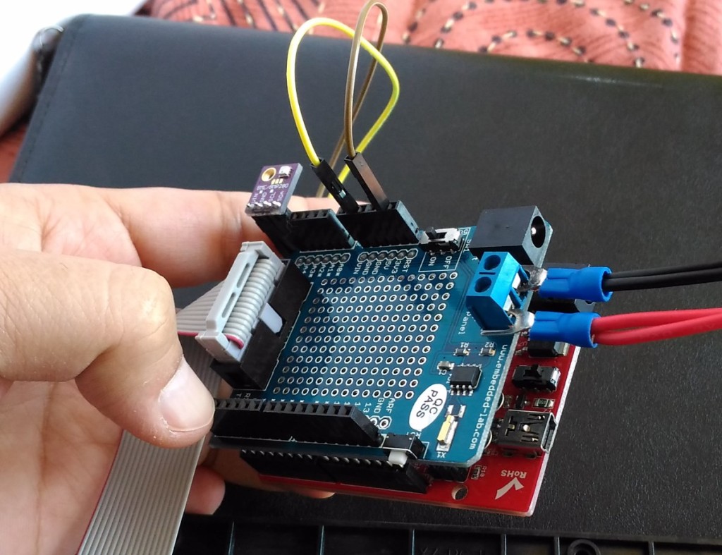
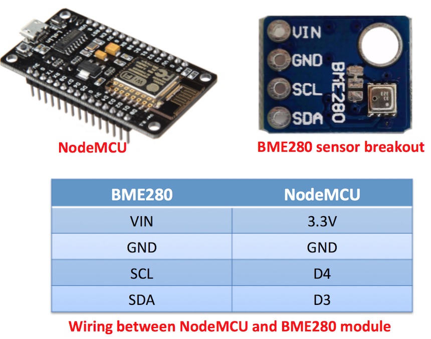
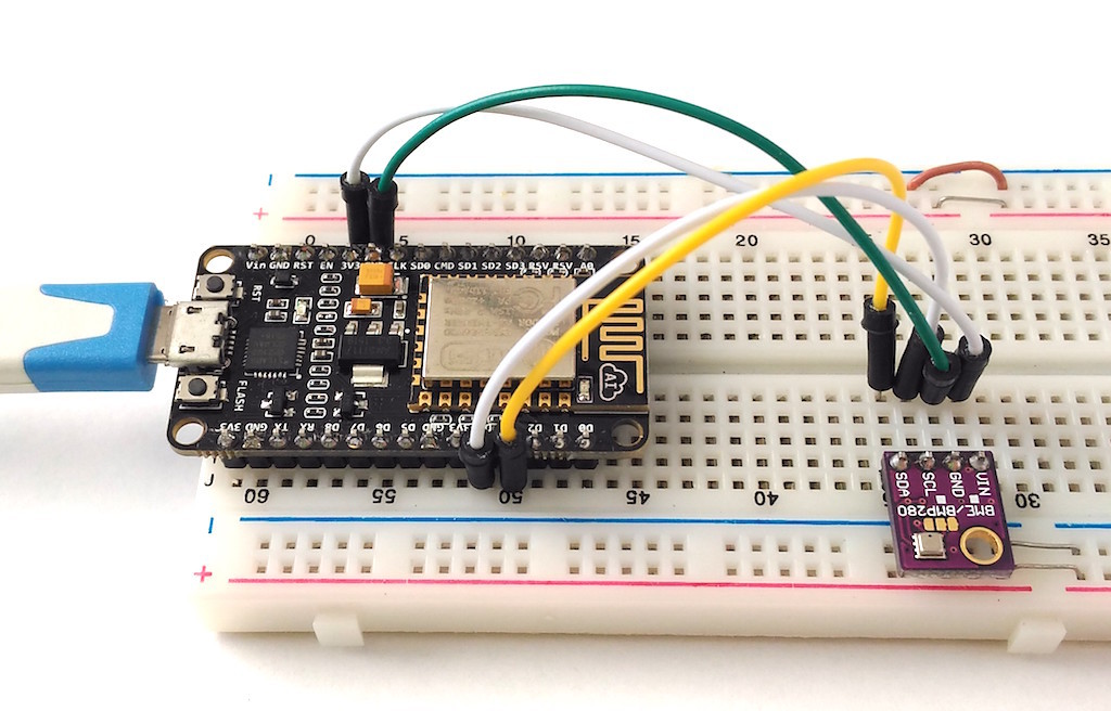
This project requires minimal hardware components. You will need an ESP8266 development board, like NodeMCU that I am using here, a BME280 sensor module, a breadboard with some jumper wires, and a USB cable for programming the NodeMCU board.
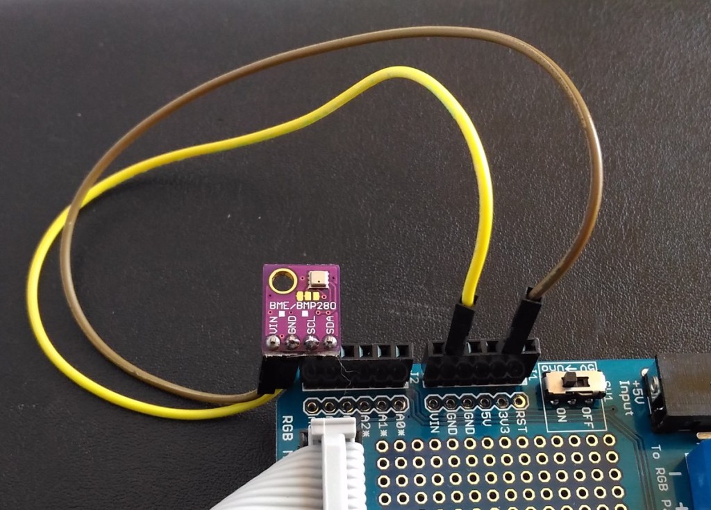
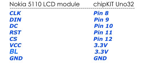
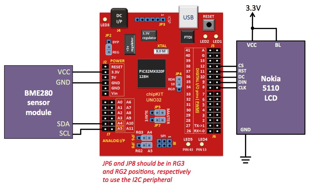
BME280 is a fully integrated environmental unit from Bosch that combines sensors for pressure, humidity, and temperature in a tiny 8-pin metal-lid LGA package of size 2.5 x 2.5 x 0.93 mm³. Because of its compact size, ease of use (BME280 supports standard I2C and SPI interfaces), and availability of supporting open-source Arduino libraries, BME280 is very popular among weather enthusiasts. In this project, the I2C data (SDA) and clock (SCL) pins of the BME sensor module are connected to the NodeMCU pins D3 and D4, respectively.
![setupserver]()
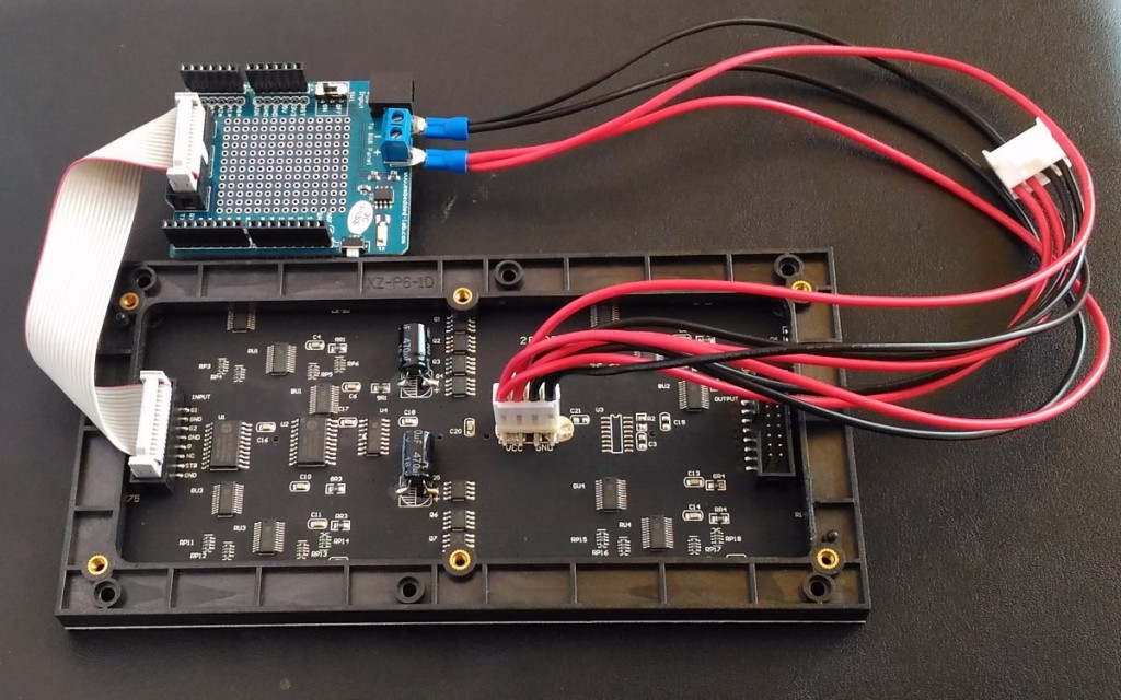
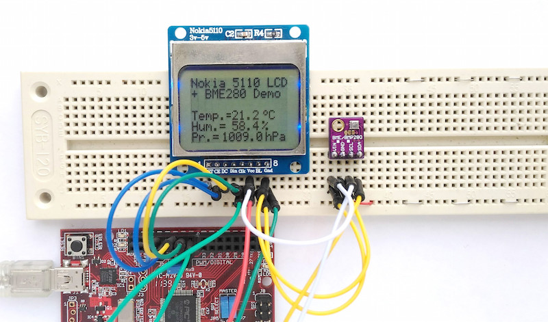
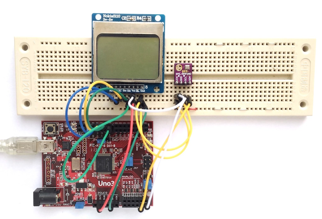
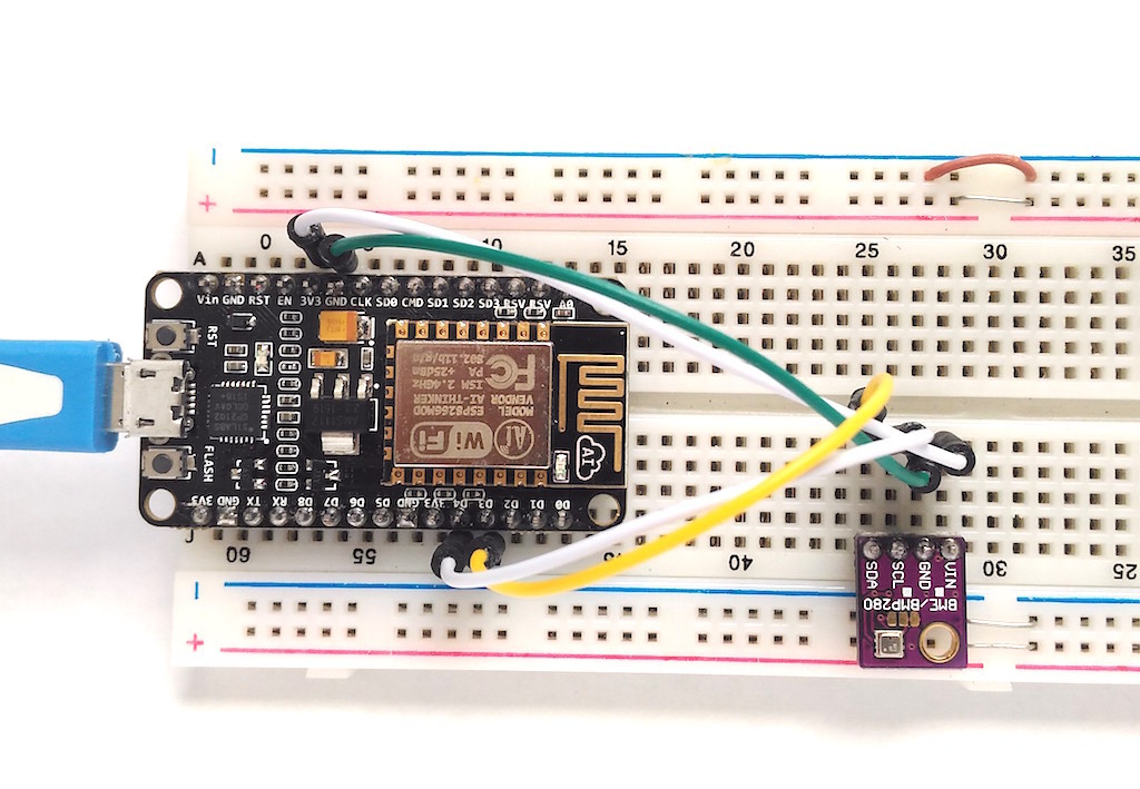
![Weather web server setup on breadboard]()
Weather web server hardware setup on breadboard
Software
The ESP8266 firmware for this project is developed using Arduino IDE. You need to install the ESP8266 core to enable the Arduino IDE for ESP8266 programming. Instructions can be found in the ESP8266 core github page or here too. You will also need the following Adafruit libraries for reading data from the BME280 sensor.
Adafruit unified sensor library
Adafruit BME280 library
The I2C address for BME280 is hardcoded in the Adafruit_BME280.h file (look for the line #define BME280_ADDRESS 0x77) inside the Adafruit_BME280_Library folder. Adafruit’s BME sensor modules are hard-wired to use the I2C address of 0x77. But the BME280 can have a slightly different I2C address (0x76) if its external SDO pin is grounded. If you are using the sensor modules from other party, it is likely that it’s address would not match with the default value in the Adafruit library. For example, for most of the BME280 sensor modules available on eBay or Aliexpress, I have found their I2C address to be 0x76. So, if you didn’t get any response from the sensor using the default address set in the Adafruit_BME280.h file, you might need to change that to 0x76.
My complete code for this weather webserver project can be downloaded from the following link:
Download BME280_webserver_code
Note that you need to edit the SSID name and password in the program to match with your WiFi network before uploading it to the NodeMCU board.
Output
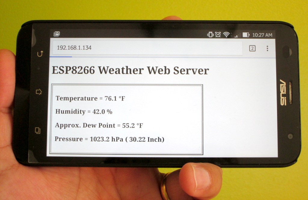
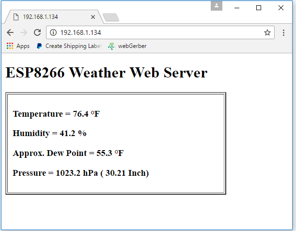
After uploading the program to NodeMCU, when the ESP8266 restarts it prints out on the serial monitor the IP address it’s allocated in the local network. In order to access the ESP8266 web server, you need to open a web browser on any computer, tablet, or smartphone connected to the same WiFi network and type in the ESP8266 IP address in the URL field and hit enter. On receiving a client request, the ESP8266 serves a webpage containing the BME sensor readings, as shown below.
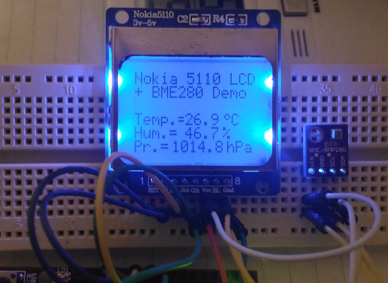
![Standalone weather web server using ESP8266 and BME280]()
Standalone weather web server using ESP8266 and BME280
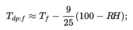
The HTML page is refreshed automatically every 15 second to get the latest sensor readings. The Dew Point is computed from temperature and humidity using the following approximation:
![Source: Wikipedia]()
Source: Wikipedia
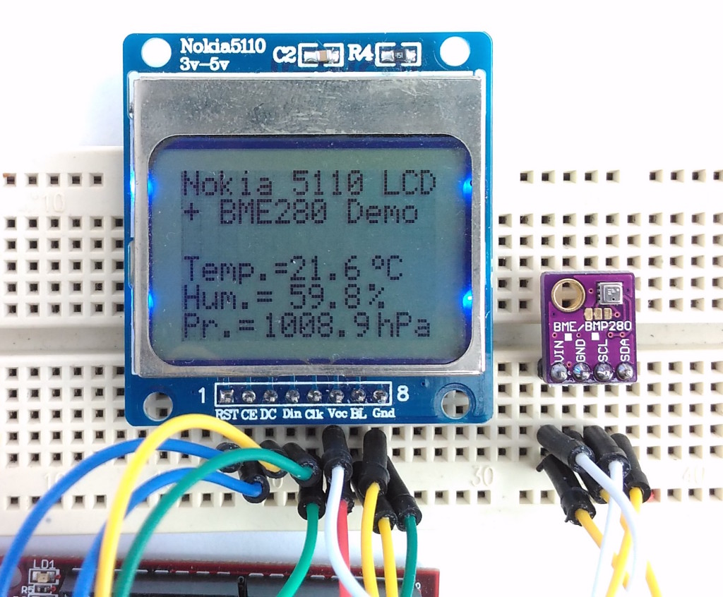
![Weather web server broadcasting BME sensor readings]()
Weather web server broadcasting BME sensor readings
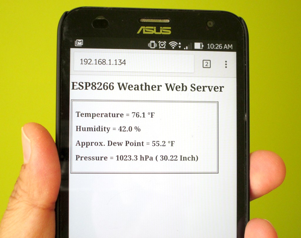
This is a very nice and handy way of monitoring the weather around us, as it allows to watch the environmental parameters on our tablets and smartphones that we are carrying all the time.
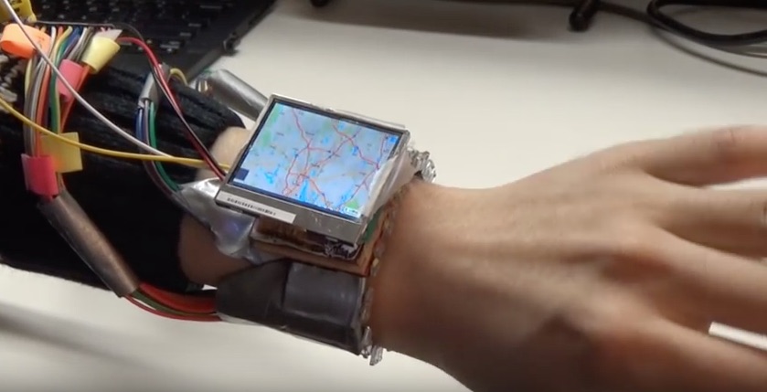
![Smartphone]()
Weather data on smartphone
Acknowledgement
Thanks to Rui Santos from Random Nerd Tutorials for sharing his DS1820-based temperature web server code. I modified his code to incorporate the BME280 sensor readings, and also added auto-refresh Meta tag to reload the HTML page automatically in every 15 sec.
The post Making a simple weather web server using ESP8266 and BME280 appeared first on Embedded Lab.
![]()