MikroElektronika, a Belgrade, Serbia-based company is well-known for producing quality software and hardware development tools for a wide range of microcontroller families, including PIC, AVR, and ARM processors. Their mikroC Pro for PIC has always been my favorite PIC compiler, and has been extensively used in my PIC tutorials and projects published on this website, for its ease of use and rich set of built-in library routines. Today, I am reviewing MikroElektronika’s EasyPIC v7, which is the latest PIC development board in their line of EasyPIC series. I would like to thank to Newark USA for providing the EasyPIC v7 board for completing this review.
Clik here to view.
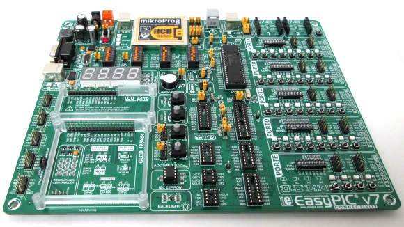
EasyPIC v7 development board
Unpacking EasyPIC v7
EasyPIC v7 comes in a colorful and protective cardboard box that can also serve as a good storage for the development board for later use. The thing I liked most about it is that the box also contains color-printed schematics and illustrative user’s manual of EasyPIC v7 along with a DVD for installing the required drivers and programming applications. The DVD also contains demo versions of mikroElektronika’s compilers as well as plenty of code examples. The EasyPIC v7 board is packed inside an anti-static bag and an USB cable is also included in the package to connect the board to the PC.
Clik here to view.
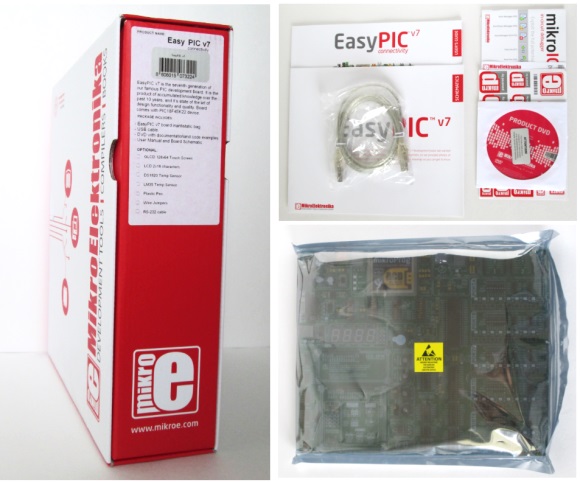
Unpacking EasyPIC v7
Main Features Highlight
EasyPIC v7, like its predecessors, is designed for rapid prototyping and development with Microchip’s 8-bit microcontrollers. It supports over 350 PIC microcontrollers, including PIC10F, PIC12F, PIC16F, and PIC18F series, and contains 8 DIP sockets to accommodate 8-, 14-, 18-, 20-, 28-, and 40-pin count PIC MCUs. The printed circuit board of EasyPIC v7 is extra thick (~3mm) and of high quality with clearly labeled components and pin functions. The board comes with the PIC18F45K22 microcontroller plugged in by default. Here I have summarized the main features of the EasyPIC v7 development board.
Clik here to view.
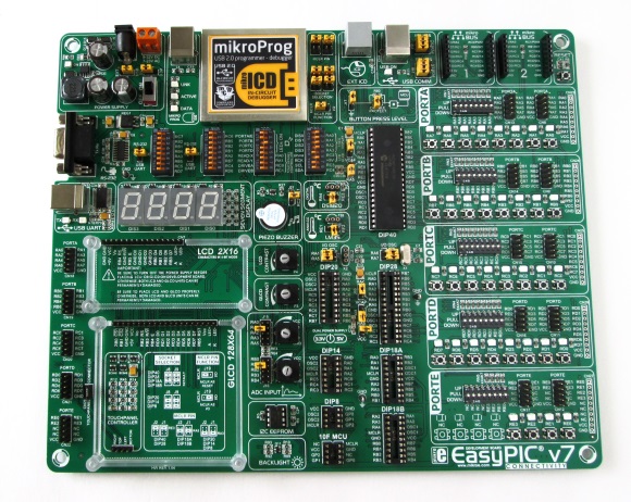
EasyPIC v7 Development Board
Power supply
EasyPIC v7 has a 5.0V switching power supply on board along with a 3.3V regulated output. A jumper selection is provided to select between 3.3V and 5.0V power supply for operation. Thus, it can be used to develop applications for both 3.3V and 5.0V series PIC MCUs. The board can be powered through a DC barrel jack, screw terminal block, or directly through an USB cable.
Clik here to view.
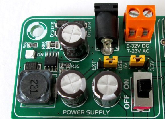
Power supply unit
On-board programmer
The EasyPIC v7 board contains mikroProg, which is an USB programmer and in-circuit debugger for 8-bit PIC MCUs, and currently support over 350 PIC MCUs. In-circuit debugging is supported by all of mikroElektronika’s compilers for PIC. The availability of on-board programmer and its integration with the compiler makes the prototyping much easier and faster. EasyPIC v7 is also equipped with an RJ-12 connector, which is compatible with Microchip’s ICD2 and ICD3 external programmers.
Clik here to view.
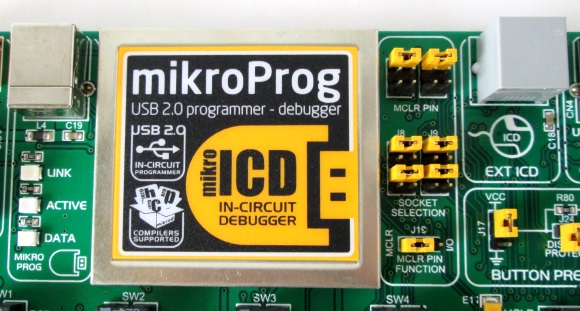
On-board programmer and debugger
I/O port organization
Unlike many other development boards, where the availability of user LEDs and tact switches are either limited or fixed to some I/O ports, the EasyPIC v7 board offers full flexibility to developers by assigning an output LED and an input tact switch for each I/O pin. MikroElektronika’s theme for EasyPIC v7 is “Connectivity“, which is justified by the presence of three IDC10 male header connectors (two on right and one on left side of the board) and one single row soldering pads for each MCU port, thus enhancing the accessibility of each I/O pin. Tri-state DIP switches are also present to enable a 4.7K pull-up (VCC), pull-down (Gnd), or floating state on any desired PORT pin. Further, the port LEDs can be enabled or disabled through DIP switches on the board.
Clik here to view.

I/O pin access and connections
mikroBUS socket
The EasyPIC v7 “Connectivity” is further enhanced by the presence of two mikroBUS sockets on board. Each mikroBUS socket consists of two 1×8 female headers, which provide access to important peripheral pins of the PIC MCU, including SPI, UART, I2C, ADC, etc., as well as the power supply pins. It allows a simple Plug-and-Play solution for connecting mikroElektronika’s several dozens of accessory boards (called Click Boards) to EasyPIC v7. Click boards are available for adding GPS, WiFi, MP3 decoding, Bluetooth, CAN, IrDA, GSM, Ethernet, and tons of other capabilities to the EasyPIC v7 board.
Clik here to view.
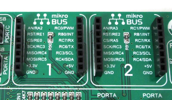
mikroBUS sockets further enhance the connectivity of EasyPIC v7
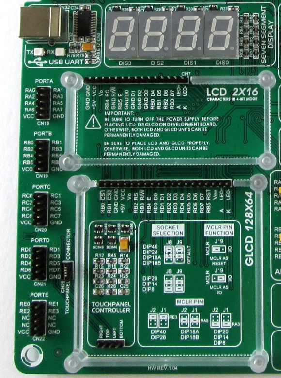
Seven segment LED and LCD Displays
The EasyPIC v7 development board provides a secured connecting socket and necessary interface support for the HD44780-based 16×2 character LCD as well as the KS108 (or compatible) driven 128×64 pixel graphical LCD. The display contrast for both LCDs is adjustable through dedicated potentiometers. Underneath the GLCD is a touch panel controller circuit that supports a 4-wire resistive touch panel glass for the GLCD. Additionally, the EasyPIC v7 also contains four seven segment LED displays that are arranged to be driven through multiplexing technique.
Serial port communication
In addition to direct access to UART pins, EasyPIC v7 also allows serial communication with the PIC MCU through a RS232 connector and a FTDI USB-UART bridge available on the board.
Clik here to view.
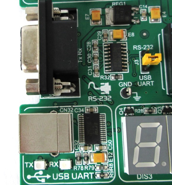
EasyPIC v7 supports RS232 and FTDI USB-UART serial communication
Miscellaneous features
Additional features include two on-board potentiometers for simulating analog signal, a piezo buzzer for experimenting with sound, sockets for DS1820 and LM35 temperature sensor ICs, a jumper for selecting the button press level (0 or 1), and an I2C serial EEPROM.
Clik here to view.
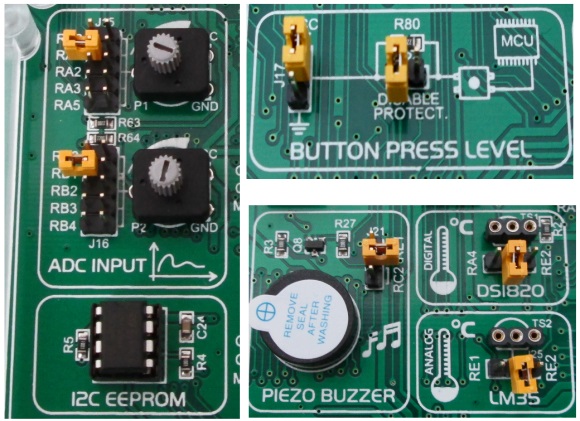
Miscellaneous features
Summary
EasyPIC v7 is one of the best PIC development boards I have ever come across for its high quality build, abundant I/O resources, highly flexible and configurable design, and support of a wide range of 8-bit PIC MCUs. The on board USB 2.0 mikroProg tool allows faster programming and real-time debugging of over 350 PIC microcontrollers. The presence of Microchip’s ICD2/3 compatible RJ-12 connector on board also allows users to use a third party programmer/debugger along with the Microchip’s MPLAB development tool. Tons of mikroElektronika’s accessory boards available in mikroBUS form factor further expands the capabilities of EasyPIC v7 beyond limits. The schematics manual and user’s guide included in the package explain very well all the on-board features and how to use them. EasyPIC v7 is a must have development board for both starters and experienced developers, and for all PIC lovers, in general.
Links:
The EasyPIC v7 board used in this review article was provided by Newark element14, which is an authorized distributer of a broad range of embedded development tools, including from TI, ST Microelectronics, Atmel, Freescale Semiconductors, and many others.
Clik here to view.
Clik here to view.
Clik here to view.
Clik here to view.
Clik here to view.
Clik here to view.
Clik here to view.