In Part 1 of this project, we described the construction of Easy Matrix, which is a cascadable 8×8 LED matrix display with MAX7219 chip on board. We developed an Arduino sketch for scrolling text display, whereby the Arduino receives text messages from its serial port and displays the message on a 8×40 LED matrix constructed by daisy-chaining five Easy Matrix modules. The Arduino firmware is also capable of receiving user commands for controlling the scrolling speed and brightness level of the display. In this part, we will discuss about extending the project to cascade 8 Easy Matrix modules and control the display over a Bluetooth connection.
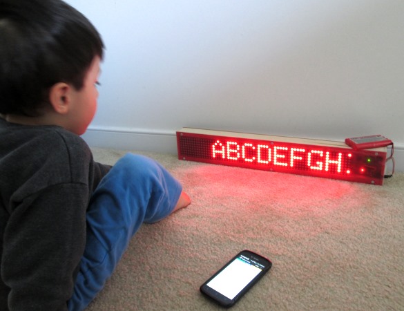
My 3 year old son using the display as a tool for learning alphabets and numbers
Power supply and display driver circuits
The 8×84 LED matrix is powered using a LM7805-based 5V regulator circuit with 1.0 Amp current capacity. For the input supply, I am using a 9.6V rechargeable battery pack. A DC wall adapter can also be used as long as it is rated 1.0 Amp or higher. The power supply circuit is very simple and shown below.
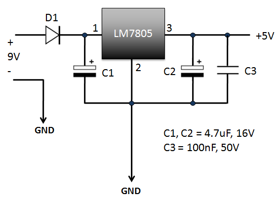
Regulated 5V power supply for the display
For the control circuit, I am using Arduino Nano version because of its smaller size. The following diagram shows the connections between the HC-06 Bluetooth module, Arduino Nano, and the LED matrix display. The HC-06 module used in this project is the one with on-board regulator for 3.3V supply. It acts as a bridge between the Arduino serial port and the Bluetooth port on your smartphone. The UART Rx and Tx pins of HC-06 and Arduino are cross-connected through two 2.2K resistors. These resistors allows to update Arduino firmware without disconnecting the HC-06 module. A 6.8K resistor is used to connect the interrupt pin (2) and the Rx pin of Arduino. The Arduino digital pins 11, 13, and 9 are used to drive the input signal lines DIN, Clk, and LOAD, respectively of the MAX7219 chip on the right-most Easy Matrix module in the daisy-chain.

Control circuit
The following picture shows a complete setup of the power supply and control circuit. Note the male headers shown on left connect to the MAX7219 signal and power lines of the Easy Matrix module.
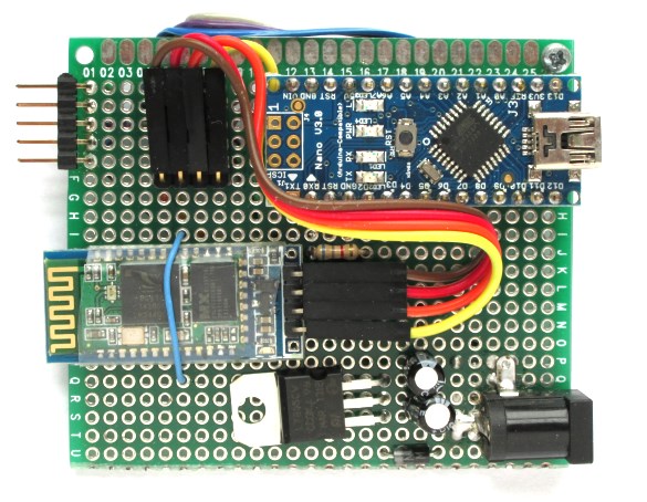
Complete setup of Arduino control circuit and power supply
The cascade of 8 Easy Matrix modules along with the Arduino control circuit are enclosed into a customized box made out of furring strip boards from the Home Depot. Two square cuts are made on one side to access to the power supply jack and USB connector.
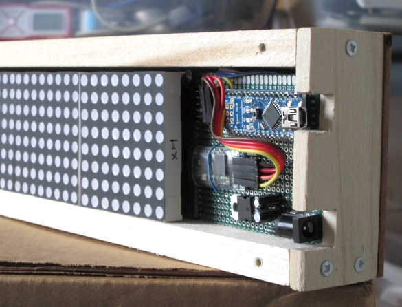
Cuts on side to access power supply and USB connectors
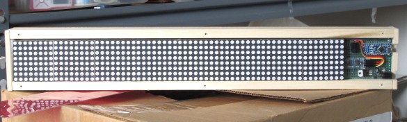
Complete project inside the enclosure
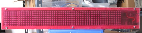
The front side is covered with a transparent red plastic to enhance the visibility of the red LED pixels
Bluetooth SPP Pro App
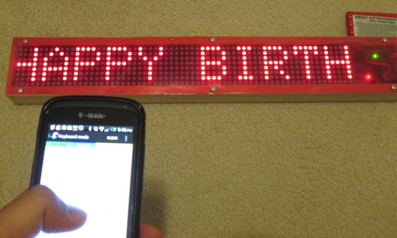
In this section, we will briefly discuss about the Bluetooth SPP Pro App and its setting to meet the requirements of this project. It is a Bluetooth client communication tool developed by Jerry.Li for Android platform and it allows to transfer data from your smartphone to the HC-06 module in ASCII or HEX format. The App searches for surrounding Bluetooth devices and displays their class and RSSI information. Once connected to the HC-06 module, the main menu shows three data transfer options, namely Byte Stream, Keyboard, and Command line mode. The Command Line mode can be used to send the display data and commands to the LED matrix just like we did in Part 1 using the Arduino Serial Monitor. It could be little tedious to type in the characters on smartphone compared to using the PC keyboard. On the other hand, the Bluetooth SPP Pro App provides 12 touchscreen buttons in Keyboard mode, where the outputs of button presses can be easily customized. This mode is useful to store text messages and send them whenever you want by simply touching the buttons. I will show the demo of it here.
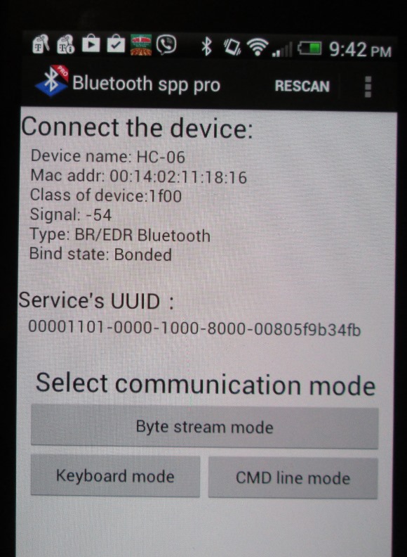
Three operation modes
The picture below shows the 12 press buttons on screen that I have customized for this project. Six buttons are customized for the control commands we have implemented in the Arduino firmware, which are Brightness level up and down, Scrolling speed high and low, Pause, and Erase. Other buttons are used to store text messages.
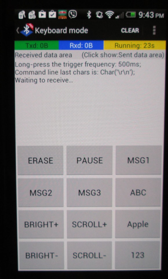
Customized buttons in Keyboard mode
The customization is very easy. First you need to select the Button set option from the option menu on top right.
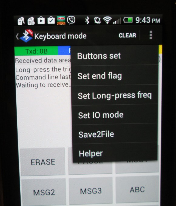
Buttini setting
And then select which button you want to customize. A Button Function setting window shows up, where you can set the name of the button and the output data that you would like to send to the Bluetooth slave (HC-06 in this case) device when it is pressed. Remember that if you want to send a text message for display, it has to be enclosed inside two parenthesis as we discussed in Part 1.
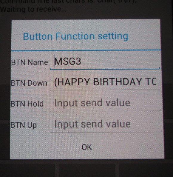
Button settings
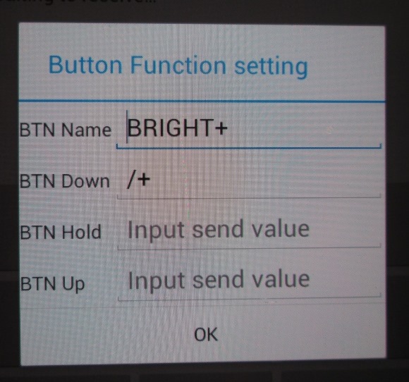
Button settings for brightness control
Once you are done with all your button settings, you can go back to operation mode by selecting Buttons set complete option from the main menu.
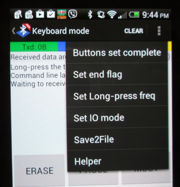
Button setting complete
Sending data and commands from smartphone
And here is a video of the display in action.
Easy Matrix kits are now available on my Tindie store.