Programmable relays are key elements in numerous automation applications such as automatic street light control, watering and pump control, HVAC, home automation, power plants automation in industries, etc. This article describes a DIY programmable relay switch using PIC16F1847 (PIC16F628A can also be used) microcontroller. It is a revised version of my previous PIC-based relay timer project with added features and some improvements in the circuit design part. Like my previous version, it also allows you to set both ON and OFF times. The maximum time interval that you can set for ON and OFF operations is 99 hours and 59 minutes. The new version features cyclic option, which means you can choose to run it in a continuous loop of ON and OFF cycles. The timer can be programmed through 4 push switches. The programming menu, relay status (ON or OFF), and number of cycles completed are displayed on a 16×2 character LCD. The timing resolution of this relay timer is 1 minute. The timer also saves the previously-set ON/OFF times and the cyclic option in its internal EEPROM so that it can retain these values after any power supply interrupt. The firmware for this project is provided for both PIC16F1847 and PIC16F628A microcontrollers.
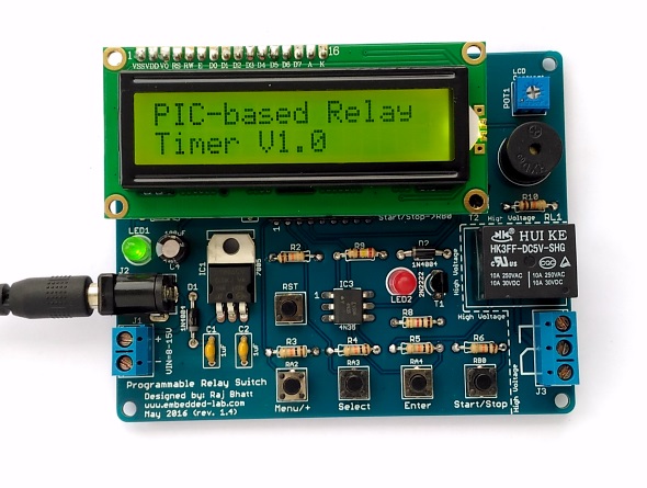
Programmable relay timer switch
Here are the summary of the features that this programmable relay switch has:
- On-board +5V voltage regulator (operates at 9-15V DC input)
- OFF and ON time setup for the relay operation
- Option for cyclic run (maximum 100 cycles, after which the timer stops automatically)
- Stores ON/OFF times and Cyclic option from previous setup into internal EEPROM
- ON/OFF timing range: 0 to 99 hours and 59 minutes with 1 min resolution
- Interactive user interface using 4 tact switches and a character LCD
- On-board buzzer alarm
You can buy the PCB for this project from Elecrow.
Circuit diagram
Let’s first talk about the hardware part of this relay timer project. It is not much different than the previous version except for a few improvements, such as an optical isolation between the microcontroller I/O pin and the relay control circuit, which will be discussed later.
Power supply: The entire circuit runs off a regulated 5V power supply derived from the LM7805 linear regulator chip (Figure 1). To minimize the heat dissipation in the voltage regulator, the recommended input DC voltage is 9V, which can be easily obtained from a DC wall adapter. The circuit board contains a 2-pin terminal block and a standard 2.1mm DC barrel jack to receive the unregulated input DC voltage. There is no power supply ON/OFF switch available on board this time.
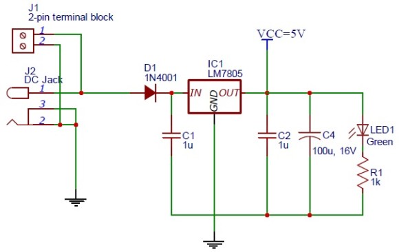
Figure 1: On-board +5V regulator circuit
Input and output
The I/O setup of this project is shown in Figure 2. There are five tact switches in this project: one for microcontroller reset, and four for user inputs. The four input switches are named as Menu/+, Select, Enter, and Start/Stop, and are pulled high under default conditions using pull-up resistors. Their functions will be described in the software section. The logic states of the 4 input switches are read by the PIC16F1847 (or PIC16F628A) microcontroller through ports RA2, RA3, RA4, and RB0. The output LCD is a standard HD44780-based display and is driven in 4-bit mode. The pin assignments for the LCD data and control signals are shown in Figure 2. The LCD backlight LED is turned on by tying its anode to +5V and cathode to GND through a 47 Ohm current limiting resistor in series.
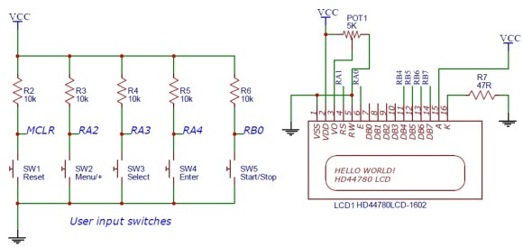
Figure 2: User inputs and LCD connections
A single NPN (2N2222) transistor-based switching circuit is implemented to drive the output relay. The switch is controlled through RB3 port of PIC16F1847. An optical isolation is provided between the microcontroller I/O pin and the relay driver using the 4N35 optocoupler. The project also includes a 5V DC buzzer (active) that beeps when the relay switch changes its state from ON to OFF and vice-versa. The relay and buzzer driver circuits are shown in Figure 3.
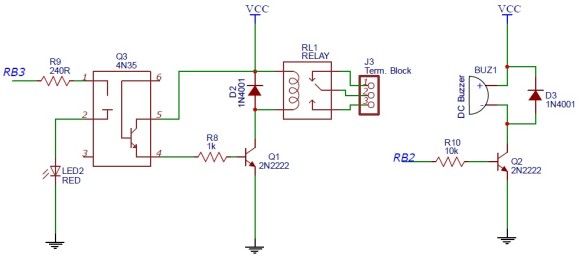
Figure 3: Relay and buzzer driver circuit
The PIC16F1847 microcontroller runs at 4.0 MHz using an external resonator. The I/O pins of the MCU, the resonator pins connections, and the in-circuit serial programmer (ICSP) header are shown in Figure 4. Because PIC16F628A and PIC16F1847 are pin-compatible, the circuit remains the same for both MCUs.
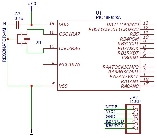
Figure 4: PIC16F628A/PIC16F1847 and external resonator connections
The PIC MCU pin assignments for the LCD, switches, relay and buzzer circuits are listed in the following table.
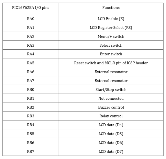
MCU pin assignments
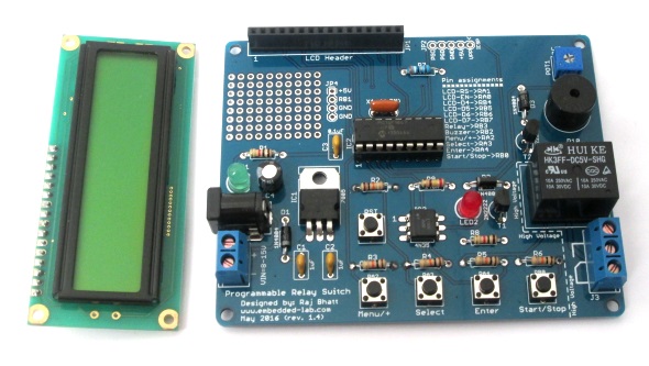
Printed circuit board
I designed a printed circuit board of the revised timer project which can be purchased from Elecrow. They ship it worldwide at reasonable shipping cost.
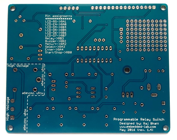
PCB: Bottom side
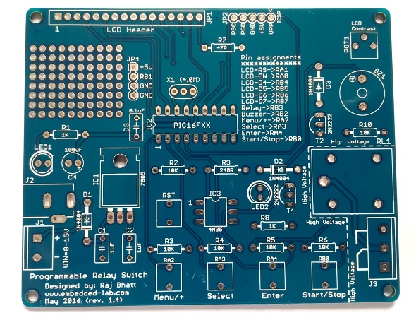
PCB: Top side
Note: The PCB also features access to the unused RB1 pin and a small prototyping area for adding extra functionality to this project. For example, an analog or 1-wire temperature sensor can be connected to this pin to build a thermostat application using the same board.
Assembled circuit board for PIC timer
Following is a complete list of components required to assemble the board.
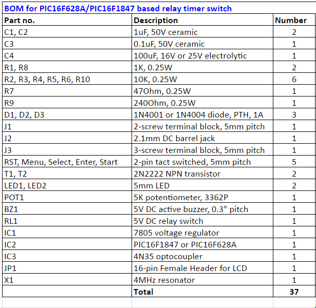
BOM for PIC timer project
The following excel sheet contains the same BOM along with the URLs for where you can buy these components.
Download PIC Relay Timer BOM Excel Sheet
Firmware
The programmable relay timer gets inputs from the 4 push buttons. Their functions are described as follows:
Menu/+ : This button allows you to navigate through various menu options such as ON time setup, OFF time setup, and Cyclic option setup. These options are displayed on the LCD. This button also serves as a digit incrementer (+) for setting ON/OFF time. The time is set in HH:MM format, which gives the minimum value of timing interval to be 1 min.
Select : This allows you to choose the currently displayed menu option on the LCD as well select between hour and minute digits. The selected digit is incremented by 1 when Menu/+ button is pressed.
Enter: When the appropriate hour and minutes are set, pressing the Enter button finalizes the time. The cyclic option is also set using this button.
Start/Stop: This push button is to start and stop the timer. After all user inputs are set, this button has to be pressed to start the timer. If the timer is already on, you can stop it at anytime during its operation by pressing this button.
Now let’s see how it works. Suppose, the relay switch is needed to be turned on after 15 minutes for 10 minutes. This means the OFF time is 15 minutes and ON time is 10 minutes. Once the timer is started after entering the above times, the device will be turned on after 15 minutes and remained on for 20 minutes. After that it will be turned off again. If the Cyclic option is selected to 1, the timer will run in a loop and after another 15 minutes of OFF time, the relay will be turned on for next 10 minutes, and so on until it completes 100 cycles. After completing the 100th cycle, the timer stops automatically. The number of cycles completed is displayed on the right side of the first row of the LCD display when the timer is ON.
The firmware for this project is developed using mikroC Pro for PIC compiler from mikroElektronika. The time keeping is achieved using the Timer 0 module built inside the PIC MCU. The Timer0 interrupt is enabled and run with 1:256 prescaler value to create a precise 500 ms (half-second) duration. The colon symbol between HH and MM digits blinks at 1 Hz. The half-second delay is looped 120 times to construct a minute-duration. Check out my tutorial on PIC Timer-0 module to learn how to create precise delays using timers. You can download the complete project files including the source code and compiled HEX files from the following links.
Output
Here’s a demo video showing the timer features in action.
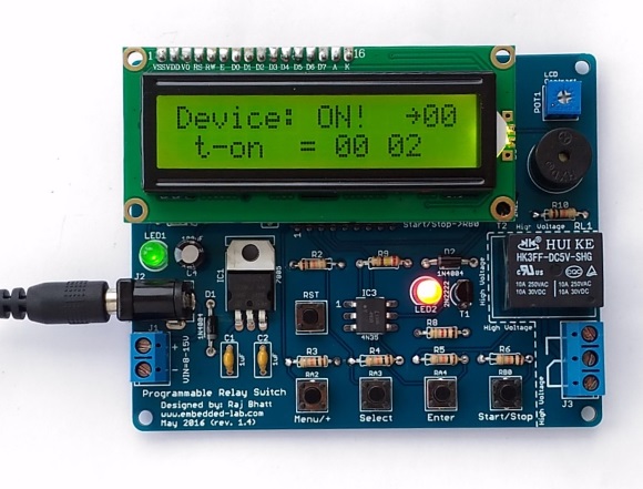
Timer is running and device is ON as indicated by red LED. 00 on top right indicates the first cycle has not completed yet. This number increment by 1 after the completion of each ON/OFF cycle (if Cyclic option is set to 1)
Click here to buy the PCB of this timer project.
References
All circuit diagrams used in this project are original and drawn by the author using the EasyEDA schematic editor. EasyEDA is a free online CAD tool for circuit layout, PCB design, and simulation.
The post Programmable relay switch using PIC MCU (revised version) appeared first on Embedded Lab.