In this blog post, I am reviewing iCircuit Technologies’ iCP12 usbStick development board and their freely downloadable SmartDAQ PC software. These two can be bundled together to construct a very basic 6-channel (analog) PC data logger.
iCP12: PIC18F2550 USB board
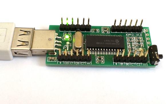
The iCP12 usbStick is a PIC18F2550 based USB development board that comes preloaded with Microchip’s USB HID bootloader that allows users to upload an application firmware directly through a PC’s USB port without any external programmer. It provides access to its I/O pins through 0.1″ pitch headers. A slide switch is also provided on board to select the operation of the board in Bootloader or Normal mode. The iCP12 usbStick board is shipped with a preloaded data acquisition firmware (HEX file is also downloadable) that emulates as a virtual COM port to PC. Thereafter, the communication between the PC and usbStick is serial. The firmware also supports basic I/O control and data logging feature. They provide a PC application named SmartDAQ that is specially developed to communicate with the usbStick (data acquisition firmware must be loaded) and control its I/O pins, PWM outputs, and record ADC inputs.
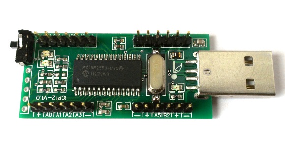
iCP12 usbStick board
SmartDAQ has a very friendly GUI with real-time waveform displays for 6 analog input channels. The time and voltage axes scales are adjustable. SmartDAQ can log the ADC data in both text and graphic form concurrently. One can utilize this feature to construct a low-cost data acquisition system for monitoring multiple analog sensor outputs such as temperature, accelerometer, gyroscope, magnetic field sensor, etc.
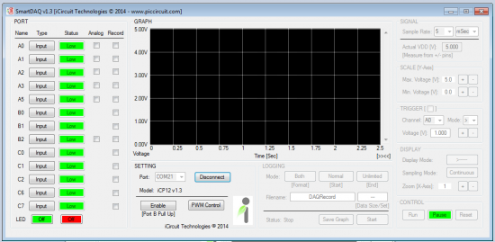
SmartDAQ GUI screen (click to enlarge)
Testing with Easy Pulse
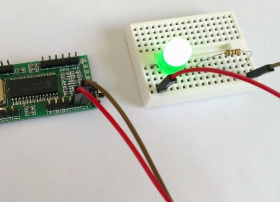
I tested the analog signal logging feature of SmartDAQ with my Easy Pulse sensor, and it worked out pretty good. I powered the sensor board through USB 5V output from usbStick and connected the analog PPG output from my Easy Pulse sensor to A0 input of the iCP12 usbStick board. When you connect the usbStick to PC’s USB port, it appears as a virtual COM port. Make sure the mode select switch on board is placed to position B (normal mode). You should select the appropriate COM port in the SmartDAQ software while connecting to the usbStick. On the GUI, PORT A0 is selected as Input, and the Analog, and Record boxes are checked. When Start and Run buttons are clicked on, the data logging is enabled and the Graph window shows the real-time waveform of the signal received at the A0 input of PIC18F2550.
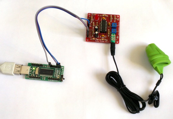
Connecting Easy Pulse output to iCP12 usbStick board analog input
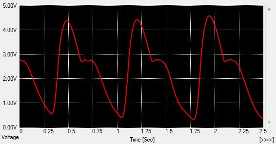
PPG signal waveform on SmartDAQ window
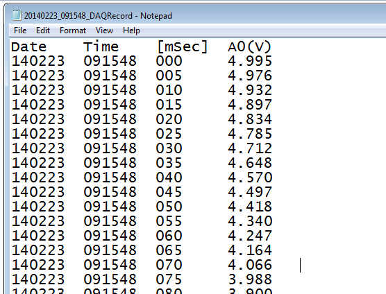
SmartDAQ ASCII output log file records ADC samples with time stamp
The log files contain all analog input voltages into ASCII format with data and time stamps obtained from the PC, which are useful for future analysis of the recorded samples. The sampling interval is adjustable from 1 millisecond to 60 minutes. Besides analog sampling and recording, you can also control individual I/O pin logic state and set frequency and duty cycles of two PWM output pins (RC2 and RC1) of PIC18F2550 through the SmartDAQ interface.
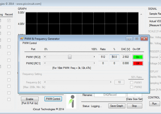
Controlling PWM pins
PWM output at 10KHz frequency and 50% duty cycle
At the price of $12.80, the iCP12 usbStick board is a real bargain, specially for hobbyists who are looking for a low cost PC data logger for capturing multiple analog sensor data. As a standalone PIC development board, the usbStick has a limitation that it lacks onboard power supply regulator.