Check out this DIY LED matrix pong game, which is Arduio-controlled and uses a rotary encoder as input device and two 8×8 bi-color LED matrix boards for game display. The LED matrix displays are driven by MAX7219 chips.
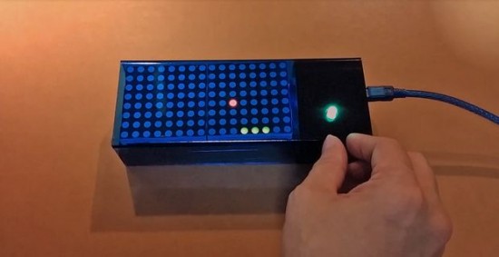
Arduino pong game
Check out this DIY LED matrix pong game, which is Arduio-controlled and uses a rotary encoder as input device and two 8×8 bi-color LED matrix boards for game display. The LED matrix displays are driven by MAX7219 chips.
Arduino pong game
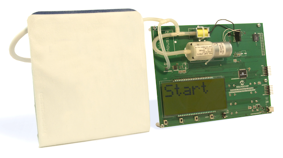
This Application Note from Microchip provides a reference design for building a non-invasive blood pressure meter using the PIC24FJ128GC010 microcontroller and MCP6N11 instrumentation amplifier.
A digital blood pressure meter measures systolic and diastolic pressures by oscillometric detection. Microchip’s digital blood pressure meter demo can measure blood pressure and pulse rate during inflation. The Measurement While Inflating (MWI) principle
reduces overall measuring time, which in turn reduces discomfort caused by the pressure in the cuff.
PIC-based blood pressure meter
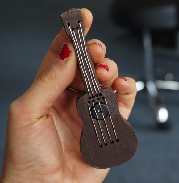
Ukulele is a small guitar-like musical instrument with four strings and has been a symbol of Hawaiian music for over 100 years. Simone Giertz has created a miniature version of it using the Arduino platform. The strings are made of conducting wires and work on capacitive sensing principle, whereas the ukulele-like sound is created through a piezo buzzer.
Arduino ukulele
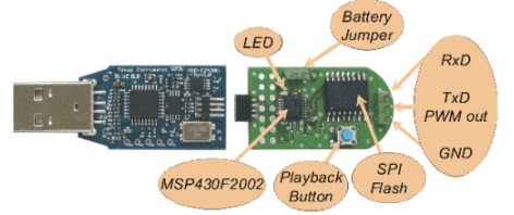
This application report discusses the implementation of a low-cost solution to store and play audio or using an MSP430. The reference design uses an external SPI flash memory, which enables flexibility of storage memory size based on the amount of playback time needed, while the low-cost MSP430F2002 MCU offers ultralow-power speech playback solution.
Audio solution with MSP430
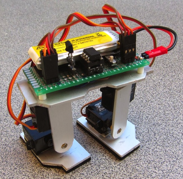
Max’s remote-controlled biped robot uses four servo motors for its legs and feet to go forward and backward. The Attiny85 microcontroller is used as its brain which receives and follows the motion commands sent from an infrared TV remote.
Attiny85 biped robot
This application note from Texas Instruments describes the hardware design considerations for making a multi-sport scoreboard that is cost efficient, portable, easy to use, and support wireless transmission of display data.
Designing an LED scoreboard
This application report describes the selection of the following: an appropriate LED display, a controller system, a communication system, and software for building the wireless LED-based scoreboard. Different techniques are included to drive the LED display from a microcontroller as well as some test results. This application report is only for displaying numerals on the scoreboard but the same concept can be applied to display alphabets. A similar concept can be extended to large LED-display modules with multiple 16 × 16 or 24 × 24 matrices.
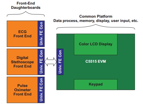
Texas Instrument’s medical development kit (MDK) is based on the C5515 DSP and consists of individual analog front-end boards forvECG, digital stethoscope, and pulse oximeter. This application note describes the implementation of digital stethoscope using the front-end board of MDK and sensor to capture the acoustic sound waves of the heart and lungs. The board contains the necessary circuitry for signal conditioning and acquiring signals from the sensors.
Stethoscope implementation on MDK board
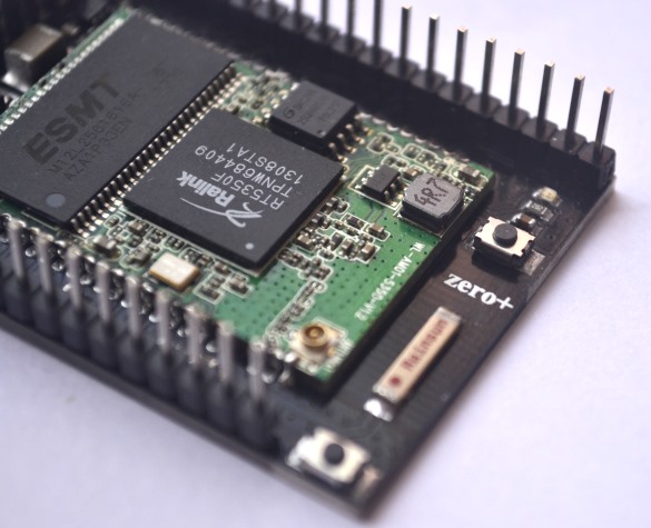
Zero Plus is a new open-source wifi module for Internet of Things applications. This project is currently being crowdfunded on Indiegogo. With RT5350 wifi SoC on board, Zero Plus provides a high performance 360 MHz CPU for advanced applications such as Wi-Fi data processing, etc. In addition, the RT5350 offers a variety of hardware interfaces (SPI/I2S/I2C/PCM/UART/USB) to support a range of possible applications.
Zero Plus IoT development platform
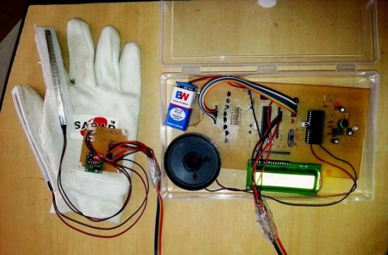
People with impaired hearing and speech often find difficult to interact with other people, mostly because their sign language is not understood by all. This Arduino-based gesture vocalizer is designed to assist those people to communicate with normal people. The device is built as a wearable glove, which converts the hand gestures into human recognizable audio. Two flex sensors for detecting bending of fingers and one ADXL335 3-axis accelerometer for getting the orientation of hand are embedded on the glove for gesture recognition. For audio conversion, the APR33A3 audio processor chip is used to storing and playing audio messages. An LCD display is also included in the project for the visual display of the message.
Gesture vocalizer
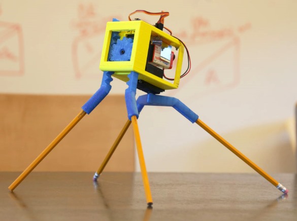
One of the most interesting applications of 3-D printing technology is building customized robot parts. It allows makers to design their own parts on a computer using affordable tools and convert the design into an actual physical product in just a few hours. Randy’s 3-D printed walking robot is a great example of 3-D printing robot parts for rapid prototyping and implementation of your ideas. The robot uses two standard servos for locomotion and are controlled by Arduino. The author also shares his 3-D printer design files and Arduino sketch to the public.
3-D printed robot
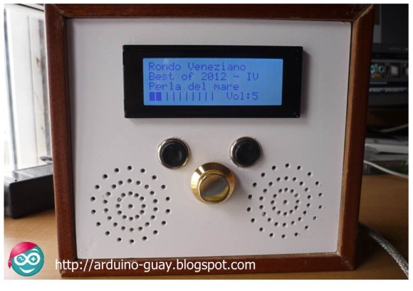
This Arduino-based standalone MP3 player was designed by Jose Daniel Herrera using the VS1002d single-chip MP3 audio decoder, which is a complete audio solution with a high-performance, low-power DSP processor along with working data memory, instruction and data RAM for user applications, serial control and input data interfaces, 4 general purpose I/O pins, an UART, as well as a high-quality variable-sample-rate mono ADC and stereo DAC, followed by an earphone amplifier and a ground buffer. His project uses a SD card module for storing MP3 files and a 4×20 character LCD for providing an user interface for displaying song menu and other information.
Arduino MP3 player
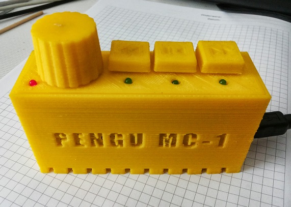
Keyboards with extra keys for quick multimedia control are a handy shortcut for geeks who love to listen to music while working on their computers. However, not all keyboards contain those extra keys. The Peng Multimedia Controller project is a DIY USB hardware device that provides shortcut keys for easy media control. It supports the basic media control features such as Next/Previous, Play/Pause and volume control. The project uses Atmega8 microcontroller which communicates with the PC through a software-only implementation of USB using V-USB. While push switches are used for Play/Pause and Next/Previous functions, a linear potentiometer is used for volume control. The casing for the project is custom-designed using 3-D printer.
USB media controller
[via HackAday]
Solar charge controller is a key component in any photovoltaic system that uses batteries to store energy. The main function of solar charge controller it to reduce the overall system maintenance and prolongs the battery life by regulating the charging voltage and current coming from the solar panels. It also protects the battery from both overcharging and deep discharging. Today, most of the solar charge controllers utilize the Pulse Width Modulation (PWM) technique to adjust the charging voltage and current according to the charging status of the batteries. For instance, if the battery gets closer to fully-charged condition, the amount of solar power delivered to the batteries is lowered by lowering the duty cycle of the PWM signal. This approach has lesser stress on batteries during charging and thus extends their battery life.
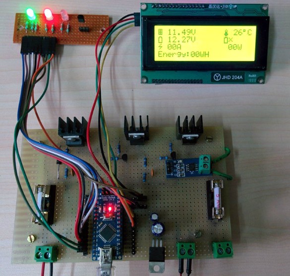
Devadish Dutta’s new DIY Solar Charge controller is also based on the PWM approach. His design uses Arduino for PWM generation and other measurements and control features. A simple resistor-divided-network is used to contruct a voltage feedback system to sense the battery terminal voltage. The feedback signal is then used to adjust the duty cycle of the PWM signal. His charge controller also implements an energy monitor system, which is really a cool feature. A 4×20 character LCD is used in the project to display the key parameters like voltage, current, power, energy, and ambient temperature. An automatic load control feature disconnects the load from the battery to prevent it from deep-discharging.
Solar charge controller plus energy meter
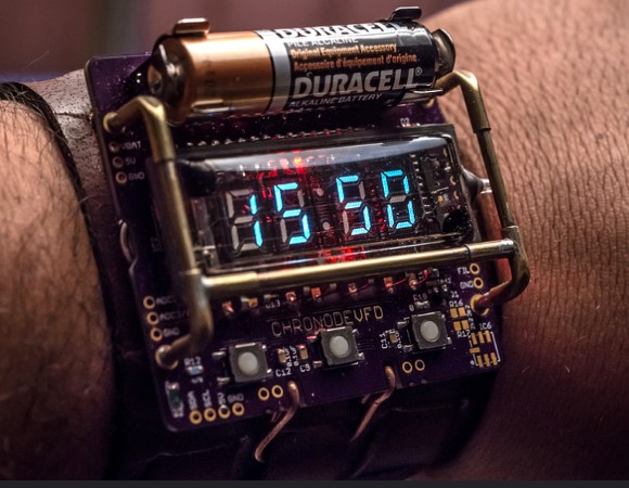
Vacuum Fluorescent Displays (VFD) are usually considered bulky, and are, therefore, mostly found in non-portable consumer-electronics gadgets such as DVD players, automobile audio system, and electric ranges. Johngineer’s ChronodeVFD is an exception to that. He used them to construct a wearable wrist watch. The ChronodeVFD uses the IVL2-7/5 VFD display tube controlled by the Maxim MAX6920 chip, which is a 12-bit output, 76V, vacuum fluorescent display (VFD) tube driver.
The core of the project is the ATMega88 microcontroller and the DS3231 RTC chip. His design also includes an analog light sensor, a BMP180 barometric/temperature sensor and a MMA8653 accelerometer. The finished watch is powered by one AA alkaline battery, which lasts for 6-10 hours.
ChronodeVFD wrist watch
Last week we looked at Randy’s walking robot made of customized 3-D printed parts. This week, he came up with this crazy idea of making underwear wake-up alarm for his lazy girl friend, who does not wake up with alarm clocks. His new project, Goodmorning Underwear, is built using the littleBits prototyping platform and a pair of panties, which vibrates to wake you up in the morning. The event to trigger the alarm are set up through Google Calender. Two vibration motors embedded into the underwear set off a gentle buzz to remind you of the event.
Underwear alarm
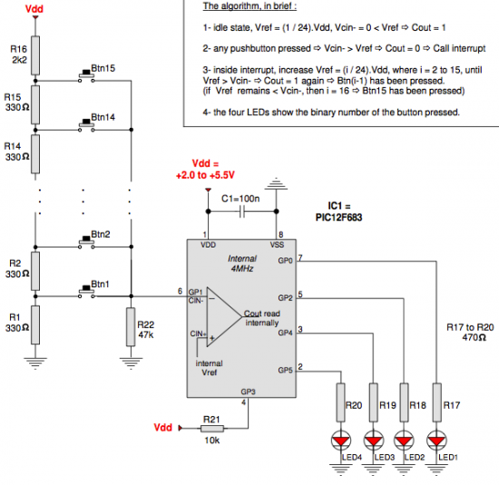
A while back I posted two articles on reading multiple tact switches using a minimal number of I/O pins of PIC microcontroller. One of them uses a resistor-divider network to create an unique range of analog voltages for each keypress. The voltage is then measured through an ADC input channel to detect which key has been pressed. Another approach was a 2-wire keypad interface using 555 timer IC configured as an astable multivibrator. The 555 timer is configured to generate a specific frequency of oscillation for each key press. However, these are not the only methods out there. Benabadji Noureddine’s recent design idea posted on EDN shows how to monitor the input logic status of 15 push switches through one input pin of PIC12F683 microcontroller. The trick is to use the I/O pin that connects to one of the inputs of PIC’s internal comparator module. The other terminal of the comparator is connected to the internal voltage reference VREF, which is selectively varied through software. He wrote a comparator interrupt routine which executes every time a pushbutton is pressed, and cycles through VREF values until the comparator output is flipped, which will indicate which pushbutton has been pressed.
Multiple tact switches on a single I/O pin
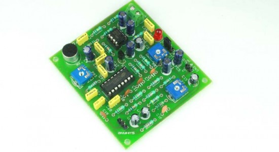
Delay effects are commonly implemented in various audio systems including Karaoke player, guitar amplifier, advanced sound processing equipment, recording studios, television etc. It basically adds an echo to the original audio by repeating the audio after a specified amount of time. Rajkumar Sharma’s new project is about building an echo generator using Holtek’s HT8970 IC, which is an echo/surround effect processor with built-in pre-amplifier, VCO, 20Kb SRAM, A/D and D/A converters as well as delay time control logic. With all these functions built inside the chip, you can easily enhance your audio with an echo effect using a minimal number of external components.
Echo generator
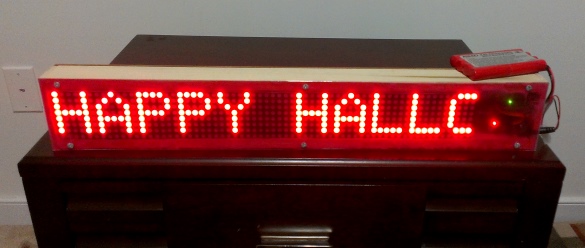
LED matrix displays are great fun. They are visually charming, and readable from a far viewing distance with a much wider angle of view as compared to many other types of electronics displays. They can display all kinds of information, including text, graphics, and animation. This project is about making a portable Bluetooth-controlled 8×64 monochromatic LED matrix (total 512 LEDs) for displaying scrolling text message. I made this display to use at home parties or other occasions for displaying greeting messages. The text data to be displayed can be sent from a smartphone using the Bluetooth connection. The display is Arduino-controlled and uses the HC-06 Slave Bluetooth transceiver module for receiving data from the smartphone. I am also using the Bluetooth SPP Pro (freely downloadable) App (developed by Jerry.Li) on my HTC One Android smartphone for sending text message to the matrix display. The complete project has got a nice enclosure made by myself using furring strip boards bought from the Home Depot. We looked at a similar project earlier made by Jollyfactory, who used bi-color LED matrices, which required two MAX7219 devices per 8×8 matrix.
Bluetooth-enabled scrolling LED matrix display
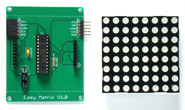
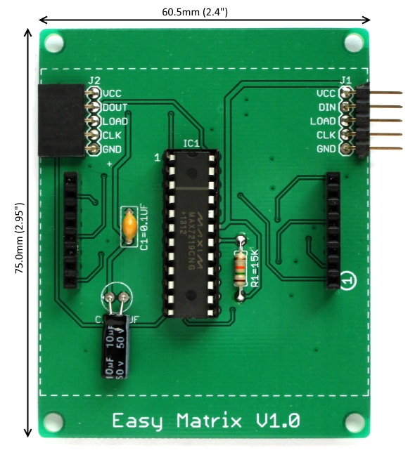
This project uses eight pieces of 60.5mm x 60.5mm (2.4″ x 2.4″) monochromatic 8×8 LED matrix modules with A-type polarity, which means the rows are common-anodes and the columns are common-cathodes. The total size of the display area thus becomes about 2.4″ x 19″ (60.5mm x 483mm). Making one big piece of PCB of that size usually costs more than making small and cascadable modules. So I designed 8×8 LED matrix modules and daisy-chained eight of them to make the 8 rows x 64 columns matrix required for this project. Each module consists of an 8×8 monochromatic LED dot matrix display with onboard MAX7219 driver chip. I have named this module Easy Matrix. It consists of a 5-pin angled male header (J1) on the right side and a 5-pin angled female header (J2) on the left side of the board. Both the headers are precisely aligned along horizontal so that the male header of one module gets easily plugged onto the female header of second module, and so on. Two 1×8 straight female headers are used as sockets to hold the LED matrix module. One of the header socket is marked with a “circle with 1” to indicate where the pin number 1 of the LED matrix display should be inserted. Four 3.5 mm mounting holes are also available at four corners of the PCB. The MAX7219 data and control signals are fed from the J1 header of the first module (the right-most module) in the chain. The complete schematic and board files can be downloaded from a link provided at the end of this section. Here are some pictures of an Easy Matrix module below.
Easy Matrix module
Dimensions of Easy Matrix board
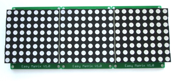
Daisy-chaining three Easy Matrix modules
If you are interested in getting all the parts for making Easy Matrix modules, look for their kits at my Tindie store.
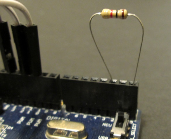
Eight Easy Matrix modules are cascaded to construct the 8×64 matrix display, which requires only three I/O pins of Arduino to drive the data and signal lines. In this project, we will be using the hardware SPI module of Arduino to drive the Data and CLK signal lines of MAX7219. So, the MOSI (digital pin 11) and SCK (digital pin 13) pins of Arduino Uno are connected to the DATA and CLK pins of the J1 header (in the right-most Easy Matrix module), respectively. The LOAD pin can be driven with any arbitrary I/O pin. We connect the Arduino digital I/O pin 9 to the LOAD pin. Besides, a 1K resistor is also required in this project, which is connected in between Arduino pins 0 (RX) and 2 (External Interrupt). This configuration generates an external hardware interrupt upon the arrival of any new serial data, and Arduino responds to it by immediately reading the data. This is important to prevent the overflow of data in the UART serial receive buffer, which has a capacity of storing only 64 bytes.
Connecting a resistor between the RX (Pin 0) and Interrupt pin (Pin 2)
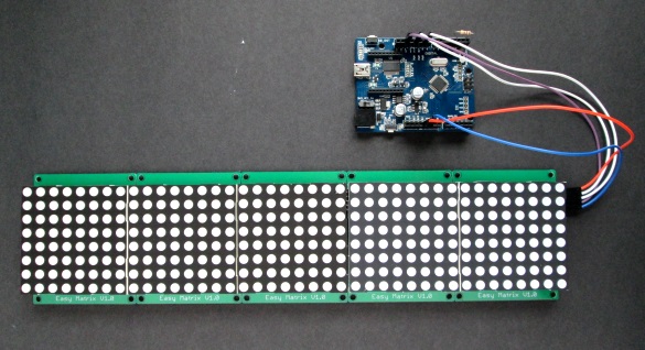
The cascade of 8 Easy Matrix modules requires approximately 1Amp of current for full brightness. The 5V regulator on Arduino Uno board cannot provide this much amount of current. So an external +5V power supply is needed. We will discuss about this in more detail later. For now, let’s use a cascade of five Easy Matrix for developing and testing the Arduino firmware. This can be powered directly from the Arduino board 5V supply. We will first test the firmware directly from the Serial Monitor terminal window by connecting the Arduino to PC through USB-UART bridge. Later we will replace the USB-UART bridge with a serial Bluetooth adapter.
Complete test setup of the project
Mark Ruys’ Max72xxPanel and Adafruit’s GFX libraries are required for this project. So install these libraries into your Arduino libraries directory, if you have not done it already. You can download the complete Arduino sketch that I have developed for this project from the link provided at the end of this section. The Arduino receives the display data and other commands, like scrolling speed control and brightness adjustment, through its serial port at 9600 baud rate. The text message to be displayed is sent by enclosing it inside a open and a closed parenthesis, whereas commands are sent by starting with a ‘/’ character. Here is a list of the commands implemented in the firmware.
When we send data to Arduino through the serial port, it gets interrupted to respond to this event. It first reads the first character to recognize if the upcoming data is a string of text message (if the first character was ‘(‘) or command (if the first character was ‘/‘), and act accordingly. Note that if the text scrolling is paused and a new display message is sent, it won’t show up on the display until the scrolling feature is resumed by sending ‘/p‘. The maximum buffer size defined for storing the incoming text message is 512 bytes (which is 512 characters).
(Note: You need to install the Mark Ruys’ Max72xxPanel and Adafruit’s GFX libraries first)
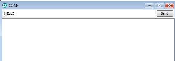
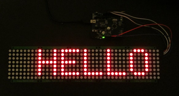
As I mentioned above, we will test the firmware first using the USB-UART connection between Arduino and PC, and later will replace the link with a Bluetooth adapter. For quick testing, I am using only five Easy Matrix modules (i.e. 8×40 LED matrix). For this, connect the Arduino board to USB port of the PCB and upload the Arduino sketch. Once the upload is completed, open the Serial Monitor program. Set the baud rate to 9600. Then type in the string (HELLO) and hit the Send button. The Arduino receives the character string and displays it on the LED matrix scrolling from right to left.
Sending text message from the Serial Monitor application
Test output on LED matrix
The following video illustrates the execution of other commands that were discussed earlier in the software section. Note that these commands begin with the character ‘/’.
In the second part of this article, we will continue this project by cascading 8 Easy Matrix modules and making an external +5V supply with higher current rating to power the display. We will also discuss about implementing a Bluetooth adapter in the project for wireless transmission of text messages to the display through the Bluetooth SPP Pro App running on an Android phone.
In Part 1 of this project, we described the construction of Easy Matrix, which is a cascadable 8×8 LED matrix display with MAX7219 chip on board. We developed an Arduino sketch for scrolling text display, whereby the Arduino receives text messages from its serial port and displays the message on a 8×40 LED matrix constructed by daisy-chaining five Easy Matrix modules. The Arduino firmware is also capable of receiving user commands for controlling the scrolling speed and brightness level of the display. In this part, we will discuss about extending the project to cascade 8 Easy Matrix modules and control the display over a Bluetooth connection.
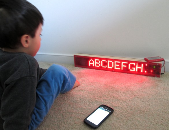
My 3 year old son using the display as a tool for learning alphabets and numbers
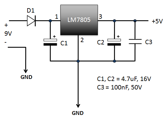
The 8×84 LED matrix is powered using a LM7805-based 5V regulator circuit with 1.0 Amp current capacity. For the input supply, I am using a 9.6V rechargeable battery pack. A DC wall adapter can also be used as long as it is rated 1.0 Amp or higher. The power supply circuit is very simple and shown below.
Regulated 5V power supply for the display
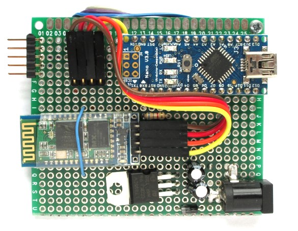
For the control circuit, I am using Arduino Nano version because of its smaller size. The following diagram shows the connections between the HC-06 Bluetooth module, Arduino Nano, and the LED matrix display. The HC-06 module used in this project is the one with on-board regulator for 3.3V supply. It acts as a bridge between the Arduino serial port and the Bluetooth port on your smartphone. The UART Rx and Tx pins of HC-06 and Arduino are cross-connected through two 2.2K resistors. These resistors allows to update Arduino firmware without disconnecting the HC-06 module. A 6.8K resistor is used to connect the interrupt pin (2) and the Rx pin of Arduino. The Arduino digital pins 11, 13, and 9 are used to drive the input signal lines DIN, Clk, and LOAD, respectively of the MAX7219 chip on the right-most Easy Matrix module in the daisy-chain.
Control circuit
The following picture shows a complete setup of the power supply and control circuit. Note the male headers shown on left connect to the MAX7219 signal and power lines of the Easy Matrix module.
Complete setup of Arduino control circuit and power supply
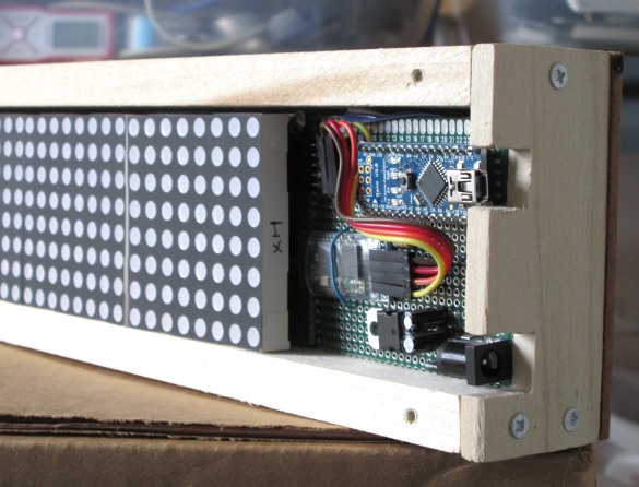
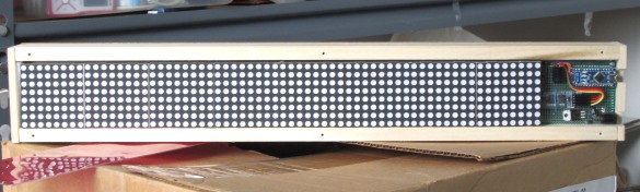
The cascade of 8 Easy Matrix modules along with the Arduino control circuit are enclosed into a customized box made out of furring strip boards from the Home Depot. Two square cuts are made on one side to access to the power supply jack and USB connector.
Cuts on side to access power supply and USB connectors
Complete project inside the enclosure
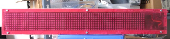
The front side is covered with a transparent red plastic to enhance the visibility of the red LED pixels
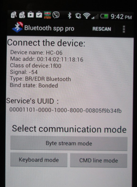
In this section, we will briefly discuss about the Bluetooth SPP Pro App and its setting to meet the requirements of this project. It is a Bluetooth client communication tool developed by Jerry.Li for Android platform and it allows to transfer data from your smartphone to the HC-06 module in ASCII or HEX format. The App searches for surrounding Bluetooth devices and displays their class and RSSI information. Once connected to the HC-06 module, the main menu shows three data transfer options, namely Byte Stream, Keyboard, and Command line mode. The Command Line mode can be used to send the display data and commands to the LED matrix just like we did in Part 1 using the Arduino Serial Monitor. It could be little tedious to type in the characters on smartphone compared to using the PC keyboard. On the other hand, the Bluetooth SPP Pro App provides 12 touchscreen buttons in Keyboard mode, where the outputs of button presses can be easily customized. This mode is useful to store text messages and send them whenever you want by simply touching the buttons. I will show the demo of it here.
Three operation modes
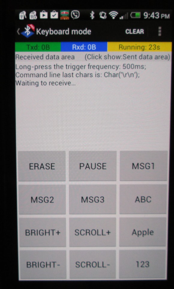
The picture below shows the 12 press buttons on screen that I have customized for this project. Six buttons are customized for the control commands we have implemented in the Arduino firmware, which are Brightness level up and down, Scrolling speed high and low, Pause, and Erase. Other buttons are used to store text messages.
Customized buttons in Keyboard mode
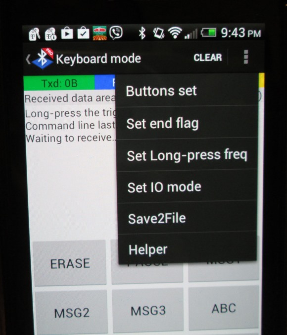
The customization is very easy. First you need to select the Button set option from the option menu on top right.
Buttini setting
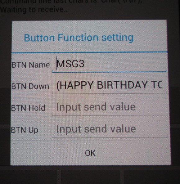
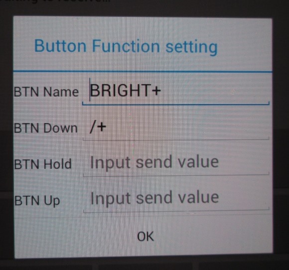
And then select which button you want to customize. A Button Function setting window shows up, where you can set the name of the button and the output data that you would like to send to the Bluetooth slave (HC-06 in this case) device when it is pressed. Remember that if you want to send a text message for display, it has to be enclosed inside two parenthesis as we discussed in Part 1.
Button settings
Button settings for brightness control
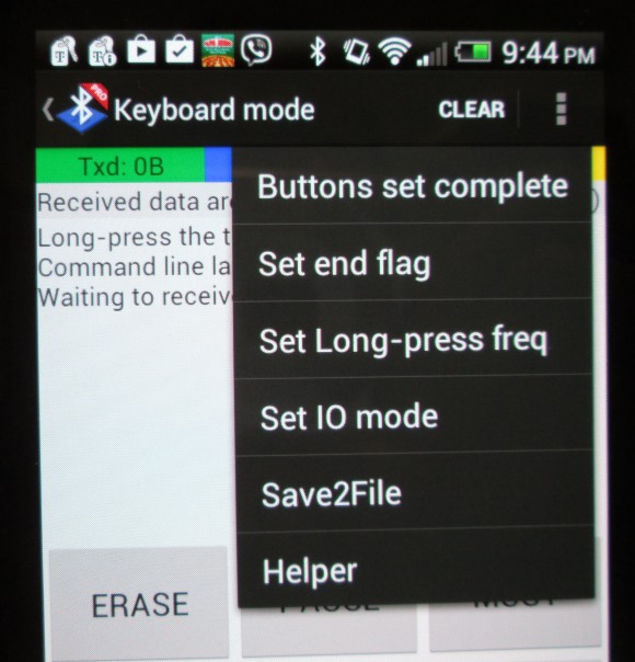
Once you are done with all your button settings, you can go back to operation mode by selecting Buttons set complete option from the main menu.
Button setting complete
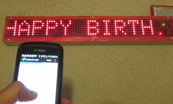
Sending data and commands from smartphone
And here is a video of the display in action.
Easy Matrix kits are now available on my Tindie store.
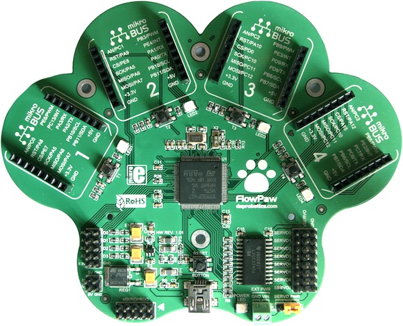
With so many other development platforms already out there in market, DSP Robotics, in collaboration with MikroElektronika, is going to introduce a new tool, FlowPaw, for rapid prototyping with electronics and robotics. FlowPaw is an expandable development board that carries a STM32F415RG MCU and four mikroBUS™ sockets, which provides a simple Plug-and-Play solution for connecting mikroElektronika’s several dozens of accessory boards called Click Boards. The Click boards are available for a wide range of applications including GPS, WiFi, MP3 decoding, Bluetooth, CAN, IrDA, GSM, and Ethernet. The FlowPaw is programmed directly through a PC USB port using FlowStone, a drag-and-drop programming tool. For those who are interested in getting a first-hand experience with FlowPaw, DSP Robitics is currently running a crowdfunding campaign over Kickstarter.
FlowPaw main board