Quantcast
Channel: Embedded Lab
Viewing all 713 articles
Browse latest View live

SatNOGS is the 2014 Hackaday Prize winner

$
0
0

Hackaday has announced the grand prize winner of the 2014 Hackaday Prize today. The winner is SatNOGs, a complete platform of an open-source satellite ground station built from readily available and affordable tools and resources.

Hackaday writes,

It opens up the use of satellite data to a much wider range of humanity by providing plans to build satellite tracking stations, and a protocol and framework to share the satellite data with those that cannot afford, or lack the skills to build their own tracking station. The hardware itself is based on readily available materials, commodity electronics, and just a bit of 3D printing.

SatNOGS provides the basis for:

  • Bulk manufacturing and deployment of affordable Satellite Ground Stations
  • Modular design for integration with existing and future technologies
  • A platform for a variety of instrumentation around Satellite Ground Station operations
  • A firm platform for a Ground Station collaborative network (one to one, one to many, many to many)
  • A community based approach on Ground Station development
  • A solution for massive automation of operator-less Ground Stations based on open standards
SatNOGS: An open-source networked ground station

SatNOGS: An open-source networked ground station

SA

SatNOGS is built using readily available and affordable tools and resources 

The post SatNOGS is the 2014 Hackaday Prize winner appeared first on Embedded Lab.


LPC1114 controlled Midi Synthesizer

$
0
0

Matt Sarnoff built this digital monophonic synthesizer using the NXP LPC1114FN28 ARM Cortex-M0 microcontroller and MCP4921 SPI DAC. It is a midi synthesizer with following features:

  • 4 oscillators; sawtooth or pulse with adjustable duty cycle with coarse and fine tuning
  • 2-pole (“Chamberlin”) state-variable filter with lowpass, highpass, and bandpass modes
  • Attack-release envelopes for amplitude and modulation
  • Low-frequency oscillator with four shapes (triangle, ramp, square, random)
  • LFO and/or modulation envelope can affect filter cutoff frequency, pitch, and pulse width
  • Keyboard tracking for filter cutoff frequency
  • Glide with 3 different rate presets
  • MIDI input; monophonic with last-note priority
  • 250kHz, 12-bit output
  • Powered by 3 AA batteries
ARM-powered midi synthesizer

ARM-powered midi synthesizer

The post LPC1114 controlled Midi Synthesizer appeared first on Embedded Lab.

Programmable lithium battery charger shield

$
0
0

Electro-Labs has posted a new project about making a programmable lithium battery charger shield for Arduino. The shield schematic and printed circuit board are designed using the SoloPCB tools, a Windows-based PCB designing tool from FabStream. The charger shield consists of a Nokia 5110 LCD and four tact switches for user interface, which allows users to program the charging voltage and current. Their design also features the ability to monitor the battery status before and during charge.

The circuit is based on LT1510 Constant Current/Constant Voltage Battery charger IC from Linear Technology. LT1510 uses the PCB ground plane as heat sink during operation. The four tact switches allows user to navigate through various features, which include setting the battery cut-off voltage and the maximum charge current, check the battery status, start and stop charging, etc. The charger stores the last set charging thresholds into Arduino’s internal EEPROM, so that at next startup the user don’t have to enter these values again. This lithium battery charger uses Arduino analog input pins A0 and A1 to sense the battery voltage and the charge current, respectively.

DIY Lithium battery charger shield

DIY Lithium battery charger shield

The post Programmable lithium battery charger shield appeared first on Embedded Lab.

Arduino-controlled self-balancing dicycle

$
0
0

XenonJohn’s has made this two-wheeled self-balancing scooter, which is Arduino-controlled and uses the ADXL345 accelerometer and the ITG-3200 MEMS gyro together to form an Inertial Measurement Unit (IMU). The Arduino MEGA board analyses the outputs from the IMU and signals the Sabertooth dual 25A motor driver (which in turn drives two 24V brushed gear motors) to maintain the balance while you are riding. A 4×20 character LCD provides you status updates during the ride. The motors are powered with a 24V battery, while the control circuit including the Arduino receives the power from six AA batteries.

Arduino-controlled dicycle

Arduino-controlled dicycle


The post Arduino-controlled self-balancing dicycle appeared first on Embedded Lab.

Turn-taking logger

$
0
0

Conversion analysis (CA) is a disciplined approach of studying natural conversations to understand how participants interact and respond in their turns at talk. The input data for CA is derived from audio or video recording of naturally occurring talk. Turn-taking is considered to be the basic unit of speech in CA. Rachel Yalisove has posted a new instructable about her turn-taking logger, an Arduino-controlled device to monitor and record  turn-takings in a 2-person conversation. The project uses two electret microphone modules with on-board amplifiers to sense the audio levels of the two persons participating in the conversation. The two microphone outputs are continuously monitored through two ADC channels of the Arduino board, which then differentiate between the speaker and hearer by comparing the two outputs. The length of each turn is computed using a timer routine. The turn-taking logger writes out these measurements in a text file on an SD card. A push switch is used in the project to control record and stop operation, while two LEDs are used to give a visual indication of who is talking at any particular moment.

A very simple turn-taking logger for CA

A very simple turn-taking logger for CA

The post Turn-taking logger appeared first on Embedded Lab.

STM32 Internals

$
0
0

STM32 micros as we know are high-end micros and this high-end tag is not only due to its memory, speed and hardware richness. An advanced micro like this also needs advanced internal supporting hardware. Most of us know about watchdog timers from previous experiences with common 8 bit MCUs like AVR and PIC. However when it comes to STM32 the idea of watchdog circuitry is elaborated. The options available for clock are also enhanced in the STM32 micros. In this post, we will see some of these supporting internal hardware. We will examine the use and operation of two different watchdog timers – Independent Watchdog (IWDG) and Window Watchdog (WWDG), and the clock options usually found in common STM32 micros.

Clock Options

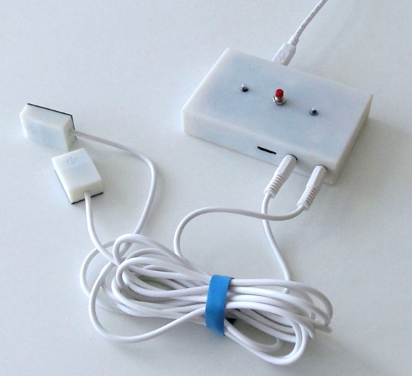
In a robust microcontroller like the STM32 there are several options for clock. At first the whole stuff may look a bit complex. Indeed it is complicated but not too difficult to understand. The simplified block diagram below shows the common clock arrangement inside a STM32F103 series MCU.

Clock Hardware

This view give a straight forward insight of the clock hardware. When it comes to software, it is very easy to configure this vast array of hardware. The good stuff about MikroC PRO for ARM and the good news for us is the fact that its IDE already ported an easy-to-use clock configuration tool just as MikroElektronika added fuse configuration tools for its PIC and AVR compilers.
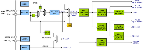
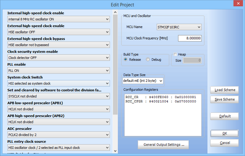
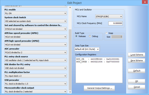
Clock Configuration Tool


This clock configuration option pops up whenever we start a new project. Alternatively we can go to the Project tab in the MikroC IDE and select Edit Project. If configured properly then it is not needed to manually code clock settings by accessing Reset Clock Control (RCC) registers. In fact we won’t be needing to add the generated values of the RCC registers anywhere in the code. These values are automatically integrated with the user code. However this feature doesn’t limit us to code RCC registers on our own.


Now let’s check out what clock sources are there in a STM32 micro. There are two basic types of clock and they are themselves divided into two speed categories. These are as follows:

  • External Sources
    • High Speed External (HSE) clock sources can be crystal oscillators, resonators or clock signal generating circuits. When using clock generator circuits, the waveform from such circuits do not necessarily always need to be square waves. HSE accepts sine and triangular waves but whatever waveform is used it must be symmetrical, i.e. 50% on and 50% off and only OSC_IN pin is used to feed the clock signal, leaving OSC_OUT pin open. Typically the HSE of STM32 MCUs accepts clock frequencies from 4 – 25MHz. If external clock circuitry is used then HSE oscillator should be bypassed. This will ensure no conflict.
    • Low Speed External (LSE) clock sources share properties similar to HSE sources but usually very accurate 32.768 kHz clock crystals are used to feed the LSE. This is the most profound use of LSE as LSE feeds STM32’s internal Real Time Clock (RTC) module.
  • Internal Sources
    • High Speed Internal (HSI) clock source is an internal fixed 8MHz clock source. It is factory calibrated and has 1% tolerance.
    • Low Speed Internal (LSI) clock source is similar to LSE but it is not very accurate. Typically its frequency is somewhat between 30 – 60 kHz. For most common uses it is considered to have a mean frequency of 45 kHz. Due to such high deviations I strongly recommend not to use it for the internal RTC.

There are prescalars at various points and these can be used to configure individual clocks of various parts of the STM32 MCU. This feature not only ensures energy saving but also aid in running various components of the micro at optimum speeds. An optional clock security unit is also available for use that can switch to HSI should HSE fail for some reason. Apart from different clock sources there is a Phase-Lock-Loop (PLL) module that can multiply either HSE or HSI to generate yet larger values of clock. In fact an 8MHz HSI or HSE clock is passed through the PLL with 9 as multiplying factor to generate full speed 72MHz clock. This also why most ready-made STM32 development boards like the ones I use for demos come with an 8MHz crystal oscillator.
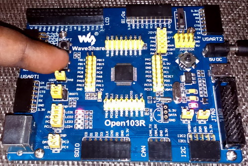
Open103R-Standard_l


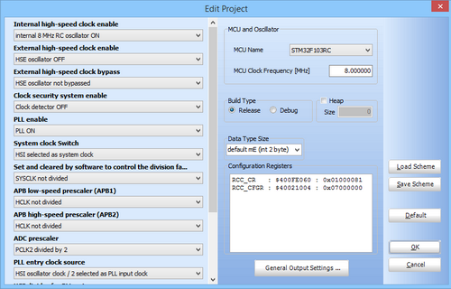
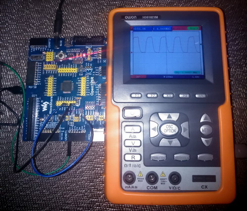
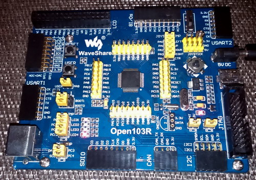
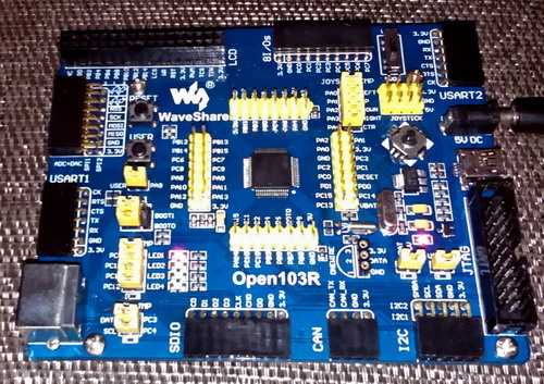
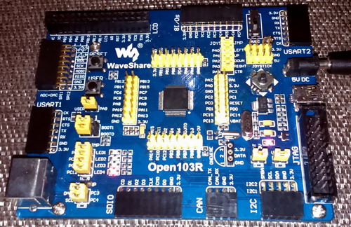
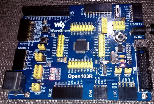
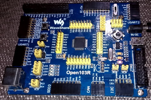
Though out this post I have used a Waveshare’s Open103R STM32F103RC delevopment board – http://www.wvshare.com/product/Open103R-Standard.htm. Like I said about development board and crystal oscillators in them this board also comes with an 8MHz and a 32.768 kHz clock crystal. As much as I have used Waveshare STM32 goods I have come across basically three categories of STM32 ARM development boards. Firstly they have Open series development boards that pack all of the features one might expect in a microcontroller development board and these boards come with easy to interface headers for connecting to external hardware like CAN communication modules, RTC modules, LCDs, etc. Secondly they also have a plug-in-module (PIM) based Open series boards that have minimum hardware and they can used either separately or with an extension motherboard. Thirdly they have Port series boards that are lighter versions of Open series boards.
When dealing with STM32’s clock, there are a few things that need well understanding. The ARM Cortex M3 is a network of instruction/data buses. Fore important buses of the Cortex are the Core System Clock, Advanced High Speed Bus (AHB), Advanced Peripheral Bus 1 (APB1) and Advanced Peripheral Bus 2 (APB2). These buses are connected as such that they are connected to the Direct Memory Access (DMA) module, SRAM, peripherals like GPIOs, ADC, timers, etc. and Cortex core. At present we need just to know about APB buses and they are of the highest importance to us. This is because we are currently dealing with the peripheral hardware of the STM32 micro and certainly not other stuffs like the DMA, Cortex core, etc. It is well known from previous posts that APB1 has a maximum operating frequency of 36MHz while APB2 can run as fast as the AHB bus – 72MHz. You can now understand why GPIOs are connected to APB2 bus instead of APB1 or any other bus and how STM32 GPIOs can achieve 50MHz switching speed. APB1 bus mostly serves communication and timer modules of the STM32. APB1 frequency is not automatically scaled to have half the speed of AHB and so we need to make sure it is not overclocked by mistake. Overclocking is not a good practice and is also not recommended by any manufacturer. To avoid overclocking the APB1 bus always use at least a prescaler of 2 whenever driving the STM32 beyond 36MHz.

Lastly we can also get clock output from a special pin called Microcontroller Clock Output (MCO). The MCO pin is usually located at PA8 pin. However to use the MCO we need to set PA8 as an Alternate Function (AFIO) output. The MCO pin can be used to clock another micro or as a time-base for another circuit or device.

Code Example:

The code example for configuring STM32’s clock and its MCO pin is literally no code at all. Everything is done by the IDE’s clock configuration tool. We’ll just need to configure the MCO pin. In all of the codes in this post, I used MikroC’s GPIO library as it easy to use and saves a lot of time.

void main()
{
     GPIO_Clk_Enable(&GPIOA_BASE);      //Enable clock for  GPIOA
     GPIO_Config(&GPIOA_BASE, _GPIO_PINMASK_8, (_GPIO_CFG_MODE_ALT_FUNCTION | _GPIO_CFG_SPEED_50MHZ | _GPIO_CFG_OTYPE_PP));  //Set PA8 as a high speed digital output
     while(1)
     {
             //To do stuffs here
     };
}

RCC 1 RCC 2


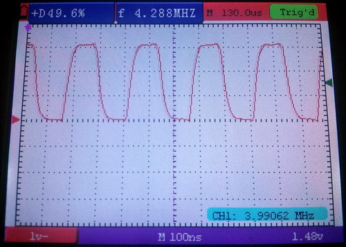
Notice how the clocks are configured. I used the HSI and didn’t use the HSE. I use HSI just to show its accuracy. I used PLL as such that the 8MHz HSI is first divided by 2 before entering the PLL stage. Thus the PLL gets 4MHz input and it then multiplies this value with 2 to generate 8MHz clock. Finally The MCO outputs a clock signal of half the value of the PLL output, i.e. 4MHz. The STM32 core however runs using HSI instead of the PLL. An oscilloscope hooked with the MCO pin registers that the clock out has a frequency of 3.99MHz. It is close enough for most applications. This is the simplest demo I could imagine.

DSC_0296 DSC_0310

Video link: https://www.youtube.com/watch?v=Fgbju2Qznkw


Independent Watchdog

As the name suggests the Independent Watchdog (hereinafter referred as IWDG) is a completely independent watchdog timer. It has separate dedicated clock and it remains operational even if the main clock of a STM32 micro fails. Thus IWDG is suited especially for those applications where it is needed just to reset a STM32 MCU on failure or due to a hang up. This is just like the regular watchdog timer use in common 8 bit MCUs. There is nothing complex about it.

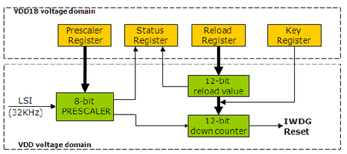
The dedicated separate clock of the IWDG hardware comes from Low Speed Internal (LSI) clock. It is not an accurate one as one might expect. This inaccuracy is due to the fact that the LSI is a RC oscillator. It has an oscillation frequency of somewhat between 30 – 60 kHz. For most applications it is assumed to have a mean frequency of 45 kHz though it is supposed to be around 32 kHz. This assumption makes it simple although there will be some deviation. Shown below is the internal block diagram of IWDG hardware:


IWDG Internal

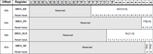
There are a few registers associated with IWDG and the register map for IWDG is shown below:

IWDG Register Map


Activating the IWDG is straight. All we need to do is to load the Key Register IWDG_KR with a predefined constant 0xCCCC. Once loaded with this value the IWDG hardware is initiated and its counter will down count from a reset value 0xFFF or a preloaded value to 0×000. When the counter counts to 0×000 count, a reset signal is issued. This is normally what we will not be wanting and so to avoid the reset we need to rewrite IWDG_KR with 0xAAAA. This will reload the counter and thus reset is avoided. At this point it is pretty much clear that we will periodically need to write 0xAAAA to the IWDG_KR register in the software. Should the software get stuck it will not be doing so and when time or count runs out, the IWDG will restart the MCU right from the initialization stage.

Before we activate the IWDG it should be configured according to our timeout need. The IWDG_PR and IWDG_RLR registers hold prescalar or divisor factor and reload values respectively. These values decide the required timeout before reset. These registers are by default write protected and so to alter their values we need to follow a sequence or otherwise write protection will not be removed. To configure the IWDG, we need to follow according to the steps below:

  1. Load IWDG_KR register with 0×5555. This will remove write protection for IWDG_PR and IWDG_RLR registers, allowing us to edit their values.
  2. Edit values for IWDG_PR and IWDG_RLR registers.
  3. Enable write protection by issuing reload command, i.e. writing 0xAAAA to IWDG_PR register.
  4. Start the IDWG by loading IWDG_PR with 0xCCCC.

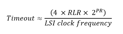
The formula for IWDG timeout is as follows:IWDG Formula

If, for example, RLR equals 180, PR equals 6 and the LSI has a frequency of 45 kHz then we roughly get a timeout of about 1000ms or 1s.

Code Example:

The code example for IWDG and the setup for it is very simple. A LED connected to PC 9 remains off until a push button connected to PA9 is pressed. This indicates initialization stage. Once pressed and held, the LED starts blinking, indicating normal operation. When the button is released, the LED stays on and then goes to reset after about one second. We, then, know for sure that the STM32 went to reset by seeing that the LED is turned off as it was during start up.

/* Function prototypes */
 
void setup();
void setup_GPIO();
void setup_IWDG();
 
void main()
{
     setup();
    
     while(1)
     {
             if(GPIOA_IDRbits.IDR9 == 0)   //If the switch is pressed
             {
                 GPIOC_BRRbits.BR9 = 1;    //Turn off LED
                 delay_ms(90);             //Wait for 90ms
                 GPIOC_BSRRbits.BS9 = 1;   //Turn on LED
                 delay_ms(90);             //Wait for 90ms
                 IWDG_KR = 0xAAAA;         //Reload IWDG
             }
     };
}
 
void setup()
{
     setup_GPIO();
     setup_IWDG();
     while(GPIOA_IDRbits.IDR9 == 1);      //Wait till the switch is pressed
}
 
void setup_GPIO()
{
     GPIO_Clk_Enable(&GPIOA_BASE);   //Enable clock for GPIOA
     GPIO_Clk_Enable(&GPIOC_BASE);   //Enable clock for GPIOC
     GPIO_Config(&GPIOA_BASE, _GPIO_PINMASK_9, (_GPIO_CFG_MODE_INPUT | _GPIO_CFG_PULL_UP));                              //Set PA9 as a digital input with pull-up
     GPIO_Config(&GPIOC_BASE, _GPIO_PINMASK_9, (_GPIO_CFG_MODE_OUTPUT | _GPIO_CFG_OTYPE_PP | _GPIO_CFG_SPEED_2MHZ));     //Set PC9 as a digital output
     GPIOC_BSRRbits.BS9 = 0;        //Turn off LED
}
 
void setup_IWDG()
{
     IWDG_KR = 0x5555;    //Disable write protection of IWDG registers
     IWDG_PR = 0x06;      //Set PR value
     IWDG_RLR = 0xB4;     //Set RLR value
     IWDG_KR = 0xAAAA;    //Reload IWDG
     IWDG_KR = 0xCCCC;    //Start IWDG
}

IWDG (2) IWDG (4) IWDG (3)


Video link: https://www.youtube.com/watch?v=_6VAUcnRPVM.

Window Watchdog

The Window Watchdog (WWDG) is an advanced watchdog timer concept. It can detect if a program is executing earlier or later than a predefined time window. Using this info it can understand if things are working perfectly or not and reset a STM32 micro if things are not okay. Unlike the IWDG or the usual watchdog timerconcept where just a counter is monitored and reloaded periodically, the WWDG is reloaded or refreshed within the predefined time window (referred just as window from now on), reloading it earlier or later than what was defined as time frame will result in a reset. Thus the WWDG is helpful in debugging software bugs apart from other uses.
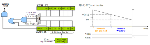
WWDG Internal


The WWDG will start its counter after setup and will down-count from a preset top value to the window value and so forth. A reset will occur when its counter counts from 0×40 to 0x3F, i.e. when the T6 bit of WWDG_CR is cleared. A programmer can only set the upper value of the window and that is because the lower value is 0×40. At 0×40 count, the WWDG will give an early wakeup call in the form of an interrupt because after this at 0x3F count it will reset the STM32 CPU. As shown in the block diagram above, window (W) bits are compared with counter (T) bits. The W bits are unaltered after setting them during initialization because these bits hold the value of the count after which we are allowed to reload the down counter or T bits. ST recommends that WWDG_CR is either configured as 0xFF or 0xCC. Doing so will ensure that the counter starts counting well above what’s stored as window. I suggest that  are set as 0x7F as it is the maximum possible value. I recommend so to avoid unnecessary minor overlooking and head-scratching mistakes.

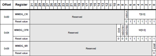
Like the IWDG, the WWDG also has few registers to configure. Here’s the register map for WWDG:

WWDG Register Map
To use the use the WWDG, we need to follow the following steps as given in the order below:

  1. Unlike the IWDG which has its separate clock, the WWDG’s clock input comes from APB1 bus and so just like enabling clocks for GPIO  ports or any other bus-driven hardware we need to enable the clock for WWDG. This is done by setting the 11th bit (WWDGEN bit) of the RCC_APB1ENR register.
  2. After enabling clock for the WWDG, we need to configure the WWDG_CR and WWDG_CFG registers along with clearing interrupt flag. Configuring these registers will configure the timing parameters like the window, prescalar, initial counter value and of course enable the WWDG. One thing to note at this point is the fact that after the WWDG is enabled in the software, it cannot be disabled without a reset.
  3. Finally if we need to use the WWDG early wakeup interrupt (EWI), we’ll need to configure the NVIC for that. I strongly suggest using this interrupt as it will run in the background and thereby needing no attention during coding. Should there be some problem with the software execution, it will automatically the reset the CPU, requiring no user intervention.
  4. In the interrupt we need to clear the interrupt flag but clearing WWDG_SR register’s EWIF bit. We will also need to reload the counter.

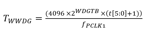
Before going further there are some certain points I must clear first because ST’s documentation is somewhat a bit confusing. The window value and the counter values are both 7 bits wide. However please notice the formula below for obtaining WWDG timeout:

WWDG Formula

Notice that the counter value t is shown to be 6 bits wide instead of 7 bits. To make things clear, first consider that   to be 0, the window value to be 95 (0x5F) and the counter’s initial value to be 127 (0x7F). From 127 to 95 counts we cannot refresh the WWDG counter as doing so will cause a reset. Between 94 to 64 counts we can reload the WWDG counter. If, for example, is 36MHz and  is 3 then  is 910µs. Thus each count takes this much time. Hence the refresh window is between  to . Reloading the counter before 29.13ms or reloading it after 58.25ms will result in reset.


Code Example:

In this demo example for the WWDG, I used a pair of LEDs designated WWDG LED and main LED. The WWDG LED is connected to PC9 and main LED is connected to PC12. There is also a button connected to PA9. What happens in the code is pretty simple. The entire working of the WWDG is handled by its ISR. When the code starts the main LED turns on and the WWDG LED is held off at the same time. This indicates the starting of the code. After this the main LED toggles every 300ms while the WWDG LED also toggles but at a much faster rate than the main LED. The WWDG LED’s toggling suggests that it has reached early wakeup count by down counting from initial value and the WWDG counter is being reloaded. The main LED toggles as to show that normal operation are going on okay. If however the button is pressed, the counter is forced to zero, causing a WWDG reset. The process repeats once the button is released and the whole thing starts over again.

/* Function prototypes */
 
void setup();
void setup_GPIO();
void setup_WWDG();
 
void WWDG_ISR()
iv IVT_INT_WWDG ics ICS_AUTO     //WWDG early wakeup interrupt function
{
   unsigned char cnt = 0;        //Temporary variables for counter and window values
   unsigned char wdt = 0;
  
   wdt = (WWDG_CFR & 0x7F);      //Read window value
   cnt = (WWDG_CR & 0x7F);       //Read counter value
  
   if(cnt < wdt)                 //If counter is less than window value
   {
       WWDG_CR |= 0x7F;          //Reload the counter
       WWDG_SR = 0x00;           //Clear interrupt flag
       GPIOC_ODRbits.ODR9 ^= 1;  //Toggle WWDG LED
   }
}
 
void main()
{
     setup();
 
     while(1)
     {
             GPIOC_ODRbits.ODR12 ^= 1;      //Toggle main LED
             delay_ms(300);                 //Wait for 300ms
             if(GPIOA_IDRbits.IDR9 == 0)    //If button is pressed
             {
                 WWDG_CR = 0x80;            //Force the counter to zero
                 while(1);                  //Get stuck into an infinity loop
             }
     };
}
 
void setup()
{
     setup_GPIO();
     setup_WWDG();
}
 
void setup_GPIO()
{
     GPIO_Clk_Enable(&GPIOA_BASE);        //Enable clock for GPIOA
     GPIO_Clk_Enable(&GPIOC_BASE);        //Enable clock for GPIOC
     GPIO_Config(&GPIOA_BASE, _GPIO_PINMASK_9, (_GPIO_CFG_MODE_INPUT | _GPIO_CFG_PULL_UP));                                    //Set PA9 as a digital input with pull-up
     GPIO_Config(&GPIOC_BASE, (_GPIO_PINMASK_9 | _GPIO_PINMASK_12), (_GPIO_CFG_MODE_OUTPUT | _GPIO_CFG_OTYPE_PP | _GPIO_CFG_SPEED_2MHZ));    
                                          //Set PC9 and PC12 as digital outputs
     GPIOC_ODRbits.ODR9 = 0;              //Turn off WWDG LED at first
     GPIOC_ODRbits.ODR12 = 1;             //Turn on main LED at first
     delay_ms(1000);                      //Wait for a second
}
 
void setup_WWDG()
{
     RCC_APB1ENRbits.WWDGEN = 1;          //Enable clock for WWDG module
     WWDG_CFR = 0x3DF;                    //Set WWDG_CFR register
     WWDG_SR = 0x00;                      //Clear interrupt flag
     WWDG_CR = 0xFF;                      //Turn on WWDG and load the counter
     NVIC_IntEnable(IVT_INT_WWDG);        //Enable NVIC for WWDG interrupt
     EnableInterrupts();
}

WWDG (2) WWDG (4) WWDG (3)
Video link: https://www.youtube.com/watch?v=E8_S2qKagDM.
It is also possible to halt both the IWDG and WWDG to halt during STM32 debugging session using the STM32’s MCUDBG register. With this feature unnecessary resets during a debug session can be avoided when STM32 core is halted.

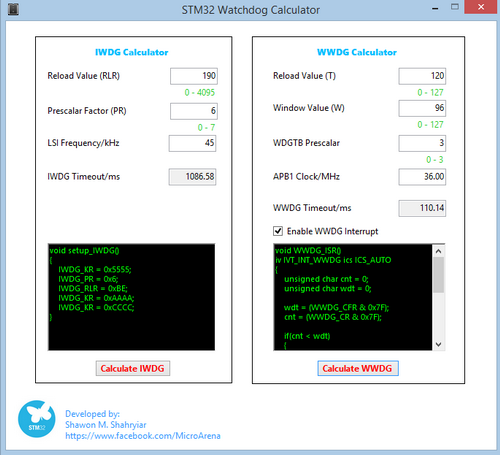
For making things easy, I have designed a GUI that can calculate parameters and generate code for both the IWDG and the WWDG. Here is a screenshot of the GUI in action.
GUI

To summarize:

  • STM32’s clock options are agile and flexible. There are various ways to achieve optimum clocking. Please refer to the RCC section of the STM32 reference manual for details.
  • Without fully realizing the STM32 clock peripheral it is pointless to go any further.
  • I personally recommend using the HSE for accurate timing although HSI is good enough for most applications. 1% deviation of frequency due to tolerance of the HSI is not a big deal.
  • I don’t recommend using LSI anywhere other than for the IWDG hardware. A very accurate 32.768 kHz clock crystal should be used for the LSE if it is to be used for the internal RTC.
  • It is not always necessary to run any MCU at max oscillator frequency as a higher operating frequency needs higher energy. This is what we should avoid if we are to design battery-operated or energy efficient devices.
  • IWDG and WWDG are different types of watchdog and should be deployed according to specific requirement. IWDG and WWDG are not interchangeable by any means.

Files: STM32 Internals.

I wish readers a useful STM32 experience. Happy coding.
Author: Shawon M. Shahryiar

https://www.facebook.com/groups/microarena

https://www.facebook.com/MicroArena


+8801970046495                   


The post STM32 Internals appeared first on Embedded Lab.

Portable GPS logger for runners

$
0
0

Daniel’s portable GPS logger is a university-funded project and is geared towards runners to record their movement. The core hardware of the project mainly consists of an LPC1778 Cortex M3 microcontroller, an Adafruit Ultimate GPS module, and a Newhaven Display 2.4″ ILI9340 QVGA LCD, which are all powered by a 500 mAh Lithium Ion battery.The GPS logger circuit also contains an on-board batter charger circuit using Microchip MCP73831T IC. It displays the current distance traveled and the time taken to travel the distance. The maps are generated from TileMill using a custom color scheme and OpenStreetMap data, and are stored in a microSD card.

The electrical hardware design (schematic/layout) and software for this GPS logger can be downloaded from GitHub.

Portable GPS logger for runners

Portable GPS logger for runners

[Via Hackaday]

The post Portable GPS logger for runners appeared first on Embedded Lab.

Black Friday/Cyber Monday 2014 Discount Coupon


Arduino OLED clock plus thermometer

$
0
0

Organic light-emitting diode (OLED) displays are the coolest displays ever made. Check out this instructable on building an Arduino controlled OLED clock that uses a DS3231 RTC module for precise time-keeping. The DS3231 is a low-cost, extremely accurate I2C realtime clock (RTC) with an integrated temperature compensated crystal oscillator (TCXO) and crystal. The project incorporates a rechargeable battery to maintain accurate timekeeping during power failure. The implementation of an interactive menu system, which is navigated through two tact switches, the time setting becomes handy. The DS3231 module uses the built-in temperature sensor to compensate for clock drift due to temperature variation, which helps to keep the accuracy to 1 or 2 minutes/year. By default, the temperature is sensed and updated by the DS3231 once every 64 seconds. However, it is possible through software to update temperature reading and oscillator adjustment done as fast as 5 times/second. The temperature measurements are also displayed on the OLED clock screen. The author uses Adafruits Graphics library to drive the OLED display, which has the SSD1306 controller.

Arduino OLED clock

Arduino OLED clock

The post Arduino OLED clock plus thermometer appeared first on Embedded Lab.

Running LED dice

$
0
0

Tons of LED dice projects with different output forms have been published online. The most common output configuration in those projects is a 3-1-3 setup (two rows of three LEDs and one LED at in the middle) of seven LEDs, which simulates the actual patterns of dots found on the six faces of a traditional dice. When it is rolled, one or more LEDs are selectively turned on to display a random number between 1 to 6. This project is about a similar LED dice but with a slightly different output form. It uses 6 LEDs which are arranged in a circular pattern and are labeled 1 through 6. They create a chasing effect when the dice is rolled. The chasing effect slows down gradually, and eventually stops at one of the six LEDs. The rolling is done by a gentle shaking of the dice horizontally. The LED dice is powered with a 3V coin cell battery and uses PIC12LF1822 microcontroller to generate a random number and drive the output LEDs.

Running LED dice

Running LED dice

Circuit diagram

The six LEDs are driven through 3 I/O pins of PIC12LF1822 microcontroller using the Charlieplexing technique. Three 100 Ohm resistors are placed in series with the I/O lines to limit the LED currents. A horizontally placed tilt switch (also known as vibration switch) is used to sense the shaking of the dice. A tilt switch is simply a tube with a tiny conductive metal ball that rolls inside it, and has two electrical contacts that are accessible from external leads. When its tilted upright, the ball rolls onto the two metallic contacts, thus short-circuiting them together. The tilt sensor along with a pull up resistor generates an interrupt signal on GP2/INT pin of the PIC12LF1822 microcontroller and the dice is rolled. A power on/off slide switch is also included in the project. In case you forgot to turn it off, the PIC microcontroller will be programmed to automatically go to sleep mode to save the power consumption. A circular shape PCB is designed for this project. The CR2032 battery holder is placed on the bottom side of the PCB, whereas rest of the electronics and LEDs go on the top side. The design files can be downloaded from the link provided at the end of this section.

LED dice circuit (click to enlarge)

LED dice circuit (click to enlarge)

Dice is made on a circular PCB

Completed dice top view

Battery goes to the bottom side of PCB

Battery goes to the bottom side of PCB

Download Eagle CAD Design Files

Firmware

The LED dice firmware was developed using mikroC Pro for PIC Compiler. For simplicity, I used the built-in rand() function to generate a pseudo-random number between 1 and 6. The rand() function in mikroC gives a pseudo-random number between 0 and 32767. It is then scaled to between 1 and 6 through a modulus division by 6 (which gives a remainder output between 0 and 5) and adding 1 to the remainder. I ran the same algorithm on a higher end PIC microcontroller (PIC18F44K22 at 16MHz) and recorded the frequency of the dice output for 100000 rolls just to see how the output distribution looks like. The mean value and standard deviation of the distribution were 16667 and 3207 (19% of mean), respectively. In 100000 rolls, number 3 exhibits the highest frequency, while 4 has the least number of occurrence. The distribution of outcome was not very impressive (that’s why it is called pseudo-random), but it should work for this basic dice project. Here is the output for 100000 rolls.

Frequency of dice outputs for 100000 rolls

Frequency of dice outputs for 100000 rolls

External Interrupt is enabled on RA2/INT pin. When the dice is rolled (shaken in this case), the tilt switch outputs a pulse signal on this pin and generates a hardware interrupt. The PIC microcontroller then displays a chasing effect with the circular pattern of LEDs, always starting from LED 1. The effect is slowed down gradually and finally stopped at the pseudo-number generated using the rand() function with some additional manipulation. The output LED is programmed to stay on for 2.5 seconds and then the PIC is put to sleep. The PIC wakes up when the dice is rolled again and an interrupt signal is issued on the RA2/INT pin.

// Define Charlieplexing lines
#define Row_A RA4_bit
#define Row_B RA5_bit
#define Row_C RA0_bit

// Define port direction and output states for each LED
const unsigned short TRISA_Data[]= \
               {0xCF, 0xCF, 0xDE, 0xDE, 0xEE, 0xEE};
const unsigned short PORT_Data[] = \
               {0x10, 0x20, 0x20, 0x01, 0x10, 0x01};
unsigned int j, i,k, random_num;

void ALL_LEDs_OFF(){
  PORTA = 0x00;
  TRISA = 0xFF;
}

void LED_ON(unsigned short num){
  TRISA = TRISA_Data[num];
  PORTA = PORT_Data[num];
}

// Interrupt service routine 
void interrupt(){ 
  if(INTCON.INTF == 1) asm nop;
  INTCON.INTF = 0;
}

void main() {
 ANSELA = 0b00000000;  // Disable analog inputs
 TRISA  = 0b00001000;  // RA3 is input only
 PORTA = 0;
 OSCCON = 0b01101000;  // Set internal clock to 4MHz
 INTCON = 0b10010000;  // Enable external hardware interrupt
 OPTION_REG.INTEDG = 0; // External interrupt on falling edge of RA2/INT pin
 Delay_ms(100);

do {
  random_num = rand()%6 ;
  for (j=0; j<=random_num+36; j++){
      i = j%6;
      LED_ON(i);
      for (k=0; k<=j/3; k++){
        Delay_ms(15);
      }
  }
  Delay_ms(2500);
  ALL_LEDs_OFF();
  asm sleep;
  asm nop;
 } while(1);
}

Download mikroC Project files

Here is a video clip of the dice in action.

The post Running LED dice appeared first on Embedded Lab.

HootLoader2 allows you to customize the ATMega16u2 USB-Serial bridge on Arduino Uno

$
0
0

We know that the newer Arduino Uno boards have two programmable microcontrollers: one is Atmega328, which is an actual Arduino processor, and the second one is Atmega16U2, which is flashed to operate as an USB-Serial converter. Nico’s HootLoader2 allows you to reprogram the Atmega16U2 with your custom sketches to add more functionalities. HoodLoader2 replaces the DFU bootloader with a CDC bootloader and comes with full Arduino compatible USB-HID core, and CDC Serial. You can also use the 7 i/o pins of the Atmega16u2 on board.

HootLoader 2 to customize the Atmega16U2 on Arduino board

HootLoader 2 to customize the Atmega16U2 on Arduino board

The post HootLoader2 allows you to customize the ATMega16u2 USB-Serial bridge on Arduino Uno appeared first on Embedded Lab.

A simple IoT demo using ESP8266 and Arduino

$
0
0

ESP8266 is a highly integrated serial-to-wifi tranceiver chip that can be used to connect any microcontroller with a serial port to a WiFi network for Internet of Things (IoT) applications. The best part of it is that the breakout board for this chip costs only $3 on Ebay, and the chip itself can be programmed/customized for a complete IoT solution. This instructable describes a simple demo of using the ESP8266 and Arduino to send temperature measurements to a remote webserver using WiFi connection. In this example, the remote server is ThingSpeak and the tenperature sensor used is Maxim’s DS18B20.

Temperature web logger using ESP8266

Temperature web logger using ESP8266

The post A simple IoT demo using ESP8266 and Arduino appeared first on Embedded Lab.

Real-time weather dashboard using littleBits

$
0
0

littleBits is a well-known development platform for rapid learning and prototyping with electronics. This real-time weather dashboard is built using the same platform to monitor current and forecasted weather information. At the heart of this project is the cloudBit, which is a single-board computer running Linux from a SD card. The cloudBit also features a WiFi adapter on board, which allows you to connect any device to the internet. For this project, the weather data for a particular location are retrived from Weather Underground, and are sent to the cloudBit using littleBits cloud APIs. The cloudBit processor then convert the weather data into appropriate voltage signals to drive servos with pointing arrows attached to them. These servos are enclosed inside modular weather boxes with the arrows pointing to current temperature, the forecasted high and low temperatures for the day, and the forecasted conditions for the day (i.e. sunny, cloudy, precipitation).

Real-time weather display using littleBits

Real-time weather display using littleBits

The post Real-time weather dashboard using littleBits appeared first on Embedded Lab.

Software realization of Real-Time Clock and Calendar

$
0
0

Dedicated real-time clock and calendar (RTCC) chips are useful in a wide range of embedded applications, such as data loggers, for accurate time-stamping of data measurements. The use of external RTCC chip frees the main processor from timekeeping responsibility and to perform other critical tasks. However, for small applications the software realization of RTCC in the main application can simplify the design and reduce the overall cost of the system. This application note from Microchip describes the implementation of software RTCC using PIC16F1827 microcontroller. The implementation provides the time (seconds, minutes, and hour), date (day, month, and year), day of week, and one alarm signal. The basis of this implementation of RTCC is the Timer1 counter, which is driven by an external 32.768 kHz crystal. The Timer1 counter can operate during Sleep mode, which helps to reduce the power consumption of the overall application if it is to be powered from a battery.

The post Software realization of Real-Time Clock and Calendar appeared first on Embedded Lab.

Automatic fish feeder with portion control

$
0
0

Dimitri from Stuttgart, Germany has made this automatic fish feeder for his special fish who needs extra care for not being overfed. So he wanted a fish feeder with reliable portion control, which he found missing in most of the existing automatic feeding devices, leading him to make one by himself. He used MSP430 as the main controller in his automatic fish feeder. A stepper motor driven by L293NE is used to control the mechanics of automatic feeding and portion control. Three tact switches are used for user inputs, whereas for visual indication of the device functioning, three LEDs are also included. Although he has found his fish feeder working smoothly so far, he is planning on doing a real test during the upcoming Christmas holidays when he will be gone and his fish feeder will be the sole caretaker of his fish.

Automatic fish feeder

Automatic fish feeder with portion control

The post Automatic fish feeder with portion control appeared first on Embedded Lab.


Aviation band VHF receiver

$
0
0

The aeronautical VHF band ranging from 118 to 137 MHz is the primary band used for aviation related communications. Dilshan R Jayakody’s new project is a simple radio receiver which is capable to receive audio communication between pilot and air traffic controller in the VHF aviation band. The receiver is based on Samsung’s KA22429 IC, which is a complete device for making a portable FM radio receiver.

Dilshan writes,

The dimension of PCB of this receiver is 70mm × 45mm and all the components except KA22429 are standard through-hole type. For the optimal results we recommended to use high gain audio power amplifier and good external antenna with this receiver. During prototyping / testing, we drive this system with 5V DC power supplyand also connect this receiver to TDA2050 AF power amplifier. At our testing we got very successful results on 124.900MHz (Colombo Airways Center), 119.100MHz (Colombo/ Ratmalana Approach) and 118.100MHz (Colombo/ Ratmalana Tower). The recorded sample on 124.900MHz using this receiver is available in here.

VHF receiver

VHF receiver

The post Aviation band VHF receiver appeared first on Embedded Lab.

Active IR gesture sensing

$
0
0

From Silicon Labs’ application note on IR Gesture Sensing:

Touchless user interfaces are an emerging trend in embedded electronics as product designers seek out innovative control methods and more intuitive ways for users to interact with electronics. Active infrared proximity motion sensing can solve this challenge. Silicon Labs Si114x proximity and ambient light sensor products are ideally suited to touchless gesturing applications such as page turning on an e-reader, scrolling on a tablet PC, or GUI navigation. The Si114x features up to three LED drivers and has the ability to sense gestures within a 7 to 15 cm product interaction region, assuming a hand as the detectable object. This document will discuss in detail how Silicon Labs implements motion sensing using infrared technology. There are two primary methods used for gesture sensing – position-based and phase-based. Position-based gesture sensing involves finding gestures based on the calculated location of an object while phase-based gesture sensing is based on the timing of the changes in signal to determine the direction of an object’s motion.

This application note focuses on detecting gestures made by a user’s hand. It is important to recognize that the concepts introduced in this application note can be applied to targets other than the hand, as long as the hardware is designed appropriately. The end application and individual system constraints will each dictate the range requirements for IR gesture sensing. Since object reflectance is the main measurable component for touchless gesturing, a hand is presumed to be the detectable object for the examples in this document. Whereas a hand can achieve gesture sensing up to 15 cm away from the Si114x sensor, a finger, with dramatically lower reflectance, can achieve gesture sensing at a range of < 1 cm for thumb-scroll type applications.

IR gesture sensing

IR gesture sensing

The post Active IR gesture sensing appeared first on Embedded Lab.

TrH Meter kits are back in stock now

$
0
0

TrH Meter is a DIY digital room thermometer plus hygrometer that displays temperature and relative humidity on 4 large (1 inch) seven segment LED displays which adjust their brightness level according to the surrounding illumination. It consists of a closed loop system that continuously assesses ambient light condition using an inexpensive light-dependent resistor (LDR) and uses that information to adjust the brightness of the display. An inexpensive DHT11 sensor is used to measure temperature and relative humidity. You can buy a complete TrH Meter kit with a preprogrammed PIC microcontroller from our Tindie store.

TrH meter displaying temperature in degree F

TrH meter displaying temperature in degree F

Note: New kits come with Red LED displays and Green PCB soldermask.

The post TrH Meter kits are back in stock now appeared first on Embedded Lab.

Turning an old Ardroid phone in to a WiFi webcam for remote monitoring

$
0
0

If you have a spare Android phone lying around somewhere with no use, you would probably need to read this Instructable to turn it into an useful WiFi-enabled webcam that could be used for remote monitoring. The author explains the technique with Motorola Droid Razr Maxx Android device, and uses IP Webcam App for video feeding. IP Webcam allows you to view the WiFi webcam video inside your WiFi network without connecting to internet, as well as outside the WiFi through VLC player or web browser. The instructable describes well how to setup a permanent local IP for your phone and configure the port forwarding on the WiFi router that will make the webcam accessible over the internet.

Making a WiFi webcam out of Android phone

Making a WiFi webcam out of Android phone

The post Turning an old Ardroid phone in to a WiFi webcam for remote monitoring appeared first on Embedded Lab.

Gesture glove to vocalize sign language

$
0
0

The Fall semester of 2014 is now over and we get to see some new and exciting embedded projects from students of Cornell published on Bruce Land’s ECE4760 class website. Monica Lin and Roberto Villalba have made a gesture glove for people with hearing disabilities. This device is intended to help them to better communicate with other people by converting their gestures into speech. For their project, they used five flex sensors to sense and quantify the bending of each finger, and the MPU-6050 (a 3-axis gyroscope and a 3-axis accelerometer) sensor to detect the orientation and rotational movement of the hand.

They write:

We designed and built a glove to be worn on the right hand that uses a Machine Learning (ML) algorithm to translate sign language into spoken English. Every person’s hand is a unique size and shape, and we aimed to create a device that could provide reliable translations regardless of those differences. Our device uses five Spectra Symbol Flex-Sensors that we use to quantify how much each finger is bent, and the MPU-6050 (a three-axis accelerometer and gyroscope) is able to detect the orientation and rotational movement of the hand. These sensors are read, averaged, and arranged into packets using an ATmega1284p microcontroller. These packets are then sent serially to a user’s PC to be run in conjunction with a Python script. The user creates data sets of information from the glove for each gesture that should eventually be translated, and the algorithm trains over these datasets to predict later at runtime what a user is signing.

Gesture glove to convert sign language into speech

Gesture glove to convert sign language into speech

And, don’t forget to watch their demo vide posted below.

The post Gesture glove to vocalize sign language appeared first on Embedded Lab.

Viewing all 713 articles
Browse latest View live