Today we are happy to announce the release of a new addition to our Easy Pulse Sensor series named Easy Pulse Plugin. Like its predecessors, the original Easy Pulse and Easy Pulse V1.1, Easy Pulse Plugin also operates on the principle of Photoplethysmography, which is an optical technique of sensing blood volume changes in tissues by illuminating the skin surface with a light source and measuring the reflected or transmitted light using a photodetector. The photodetector output contains the cardiovascular pulse wave, which is synchronized with the beating of the heart. Easy Pulse Plugin provides all necessary instrumentation and amplification on board to detect the cardiovascular pulse signal from the fingertip. The most important characteristics of Easy Pulse Plugin is that it can be easily plugged into the left headers of Arduino Uno (or its compatible clone) board for easy interfacing, and the analog pulse signal can be fed to either A0 or A1 analog input through a 2-pin jumper selection. You can buy this sensor at our Tindie Store.
![Easy Pulse Plugin]()
Easy Pulse Plugin
![asas]()
Easy Pulse Plugin is easy to interface to an Arduino Board
Features
For schematic and theory of operation, please visit our previous Easy Pulse V1.1 page. It is mostly the same circuit except the Easy Pulse Plugin only provides analog pulse signal (no digital pulse output as in Easy Pulse V1.1).
- Compatible with both 5.0V and 3.3V interface. Select the operational voltage by placing jumper JP1 on appropriate position.
- Nice and clean pulse output
- On board potentiometere for amplifier gain control (rotate CCW for increasing gain)
- Output pulse signal can be routed to A0 or A1 pin through jumper JP2.
- Easily plugs into a breadboard, Arduino Uno, chipKIT Uno32 and other compatible platforms.
- LED power indicator (LD1)
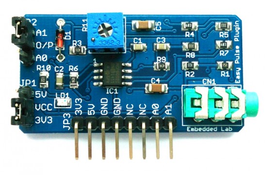
![Easy Pulse Plugin board]()
Easy Pulse Plugin board
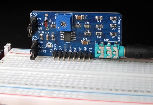
![asasa]()
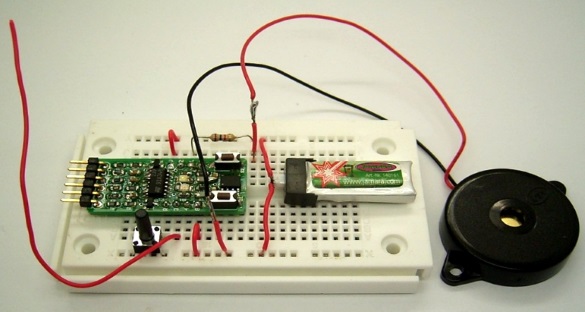
Easy Pulse Plugin on breadboard
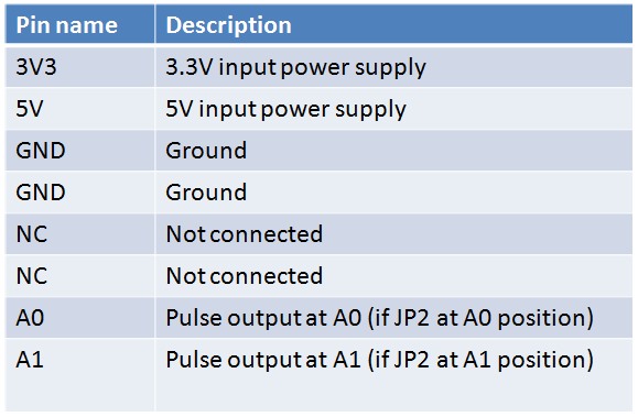
The following table shows the pin descriptions of Easy Pulse Plugin.
![Easy Pulse Plugin pin names and their functions]()
Easy Pulse Plugin pin names and their functions
Configuration Examples
Easy Pulse can be configured to operate at 3.3V or 5.0V through JP1 jumper. Similarly, the output pulse signal can be routed to either A0 or A1 pin through JP2 jumper. The following pictures illustrates two of the possible four configurations.
Picture 1 powered by 5V and output at A0
Picture 3 powered by 3.3V and output at A1
Example projects
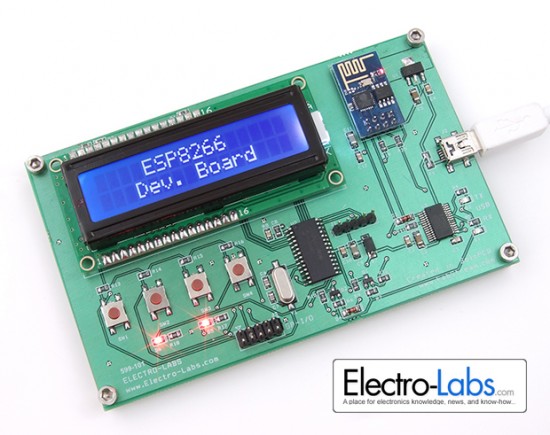
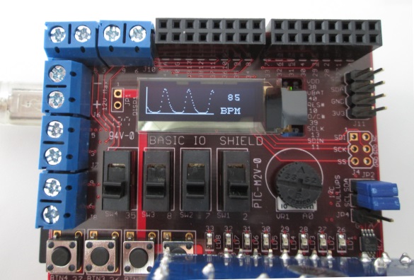
Easy Pulse Plugin and chipKit Uno 32: The first example shows a standalone digital pulse meter using Digilent’s chipKIT Uno32 board and chipKIT Basic I/O shield. The I/O shield consists of an OLED display that is used in this project for displaying the pulse waveform and the pulse rate. The details of this project can be found here. Note that the JP1 and JP2 jumpers of Easy Pulse plugin should be placed on 3V3 and A1 positions for this project.
![EPP_ChipkitUnoplusIO]()
Standalone pulse meter using Easy Pulse Plugin and chipKIT Uno32
![EPP_ChipkitUnoplusIO2]()
Pulse meter display
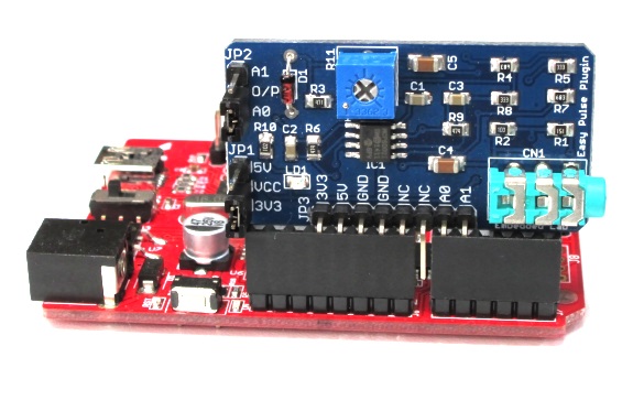
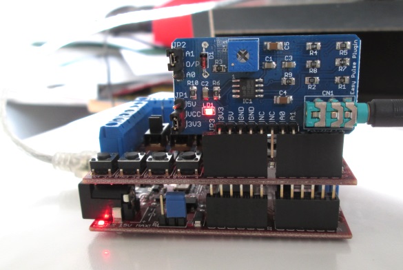
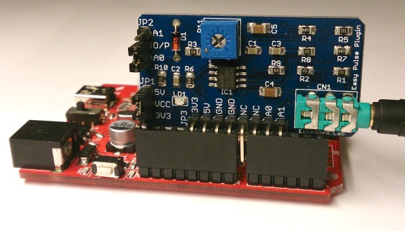
PC-based Pulse meter: This example illustrates how to make a PC-based heart rate monitor system using an Arduino Uno board and Easy Pulse Plugin. The sensor is operated at 5.0V and the output is read by the A0 anaog input pin on the Arduino board, which then transfers the data to the PC through a serial interface. A PC application is developed using Processing programming language to display the received PPG signal and instantaneous heart rate. More details on software can be found here. The following picture shows the required jumper settings and placement of Easy Pulse Plugin on Arduino Uno board.
![Jumper settings for PC-based pulse monitor project]()
Jumper settings for PC-based pulse monitor project
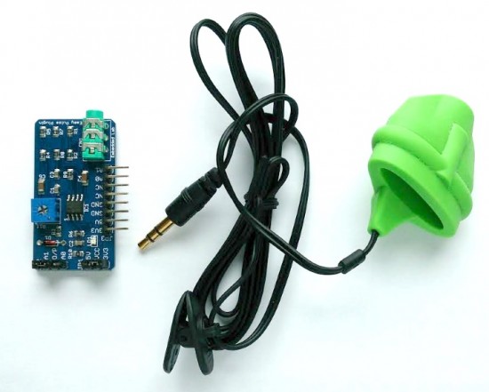
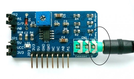
Important note: While operating the Easy Pulse sensor, make sure the sensor connector is inserted well and pushed all the way into the audio jack as shown below.
![Sensor must be plugged in well into the socket]()
Sensor must be plugged in well into the socket
Buy Easy Pulse Plugin at our Tindie Store.
The post Introducing Easy Pulse Plugin: A breadboard friendly and Arduino/chipKIT compatible pulse sensor appeared first on Embedded Lab.
![]()