Whether you want to show sensor readings, implement a navigational user interface menu, or display diagnostic information during prototyping a project, a graphic OLED display is always a cool add-on to embedded systems. In this tutorial, we will learn how to interface an I2C monochromatic OLED screen to ESP8266 (we will use EasyESP-1 board) using Arduino IDE. The OLED display used in this tutorial is SSD1306-based that can be bought for ~$5 on eBay or Aliexpress. You can also get a similar I2C OLED display with a grove connector from Elecrow for plug-and-play interfacing with the EasyESP-1 board.
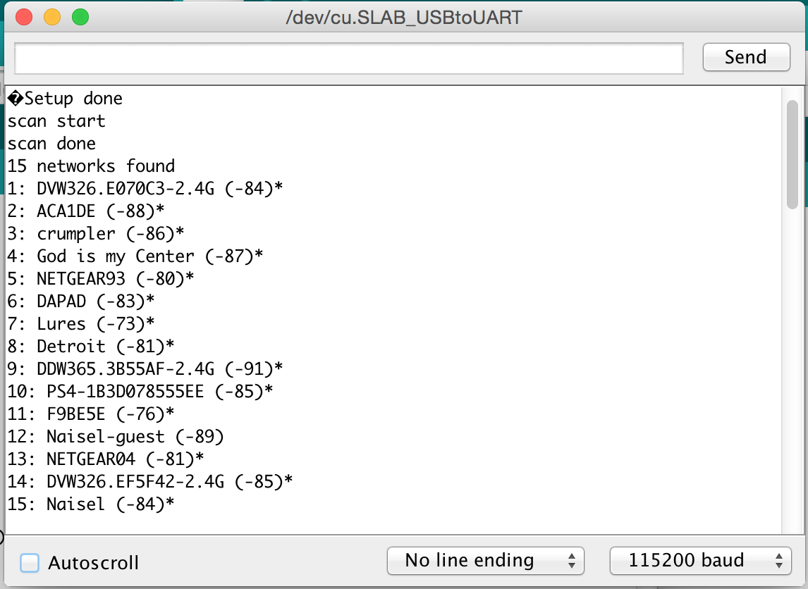
![Interfacing an SSD1306-based I2C OLED to EasyESP-1]()
Interfacing an SSD1306-based I2C OLED to EasyESP-1
Hardware Setup
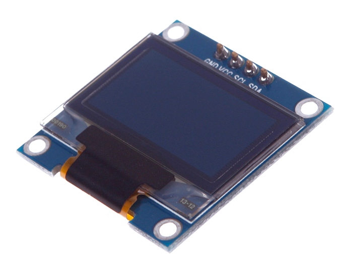
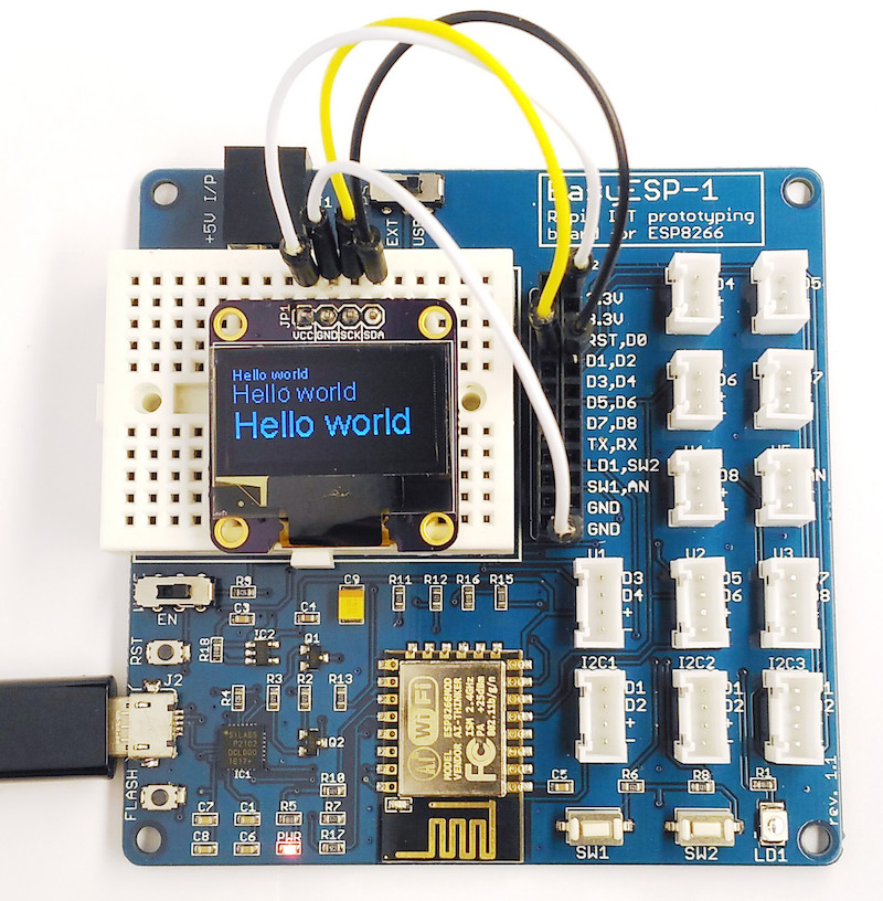
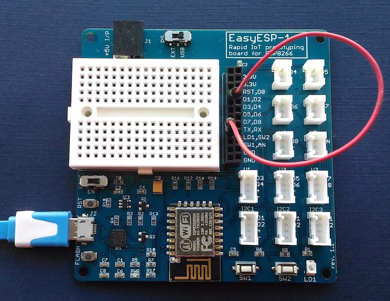
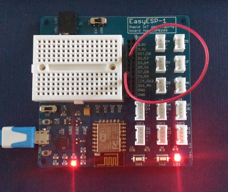
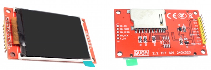
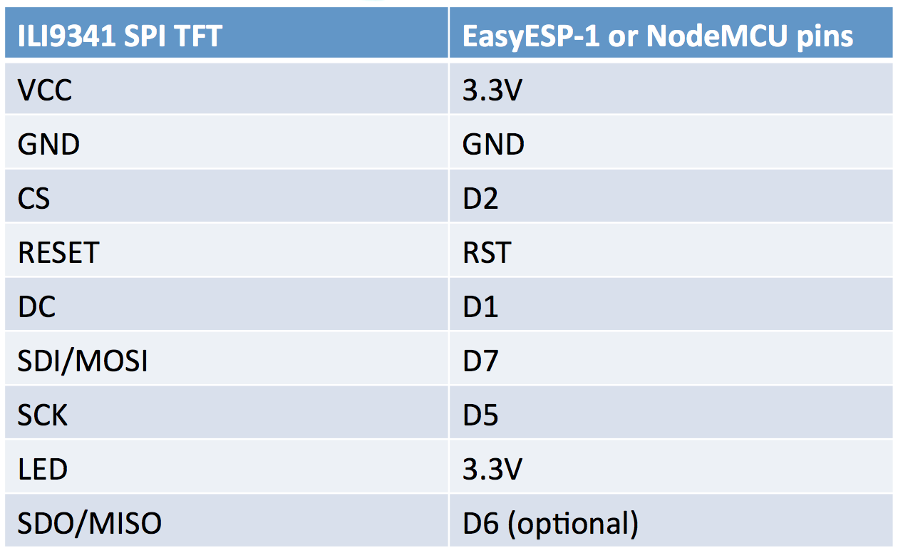
The I2C OLED breakout board chosen for this tutorial consists of a 0.96″ diagonal length display with 128×64 monochrome pixels. Despite its small size, the readability is pretty good due to its high contrast. Individual pixels are turned on or off by the on-board SSD1306 controller chip that supports both SPI and I2C interface. This tutorial uses an OLED display with I2C interface and has only four signal lines, namely VCC, GND, SCL, and SDA. For this experiment, these pins are connected to 3.3V, GND, D1, and D2 pins on the EasyESP-1 board, respectively.
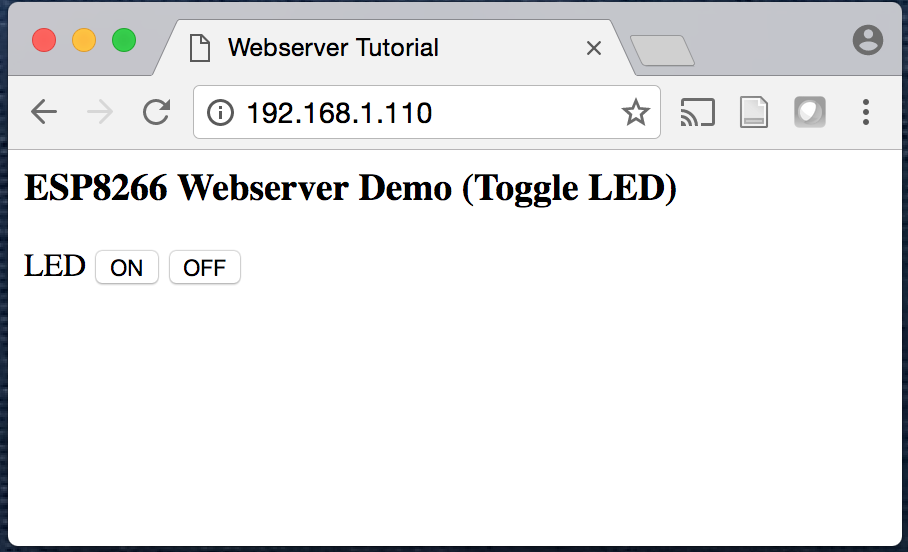
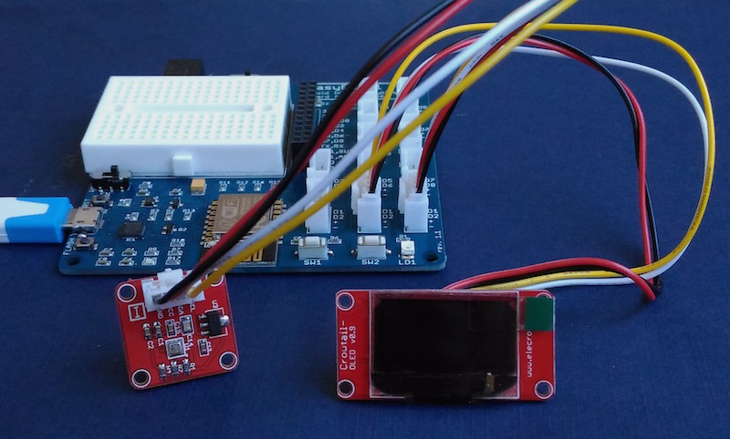
![SSD1306 based 0.96" OLED display module]()
SSD1306 based 0.96″ OLED display module
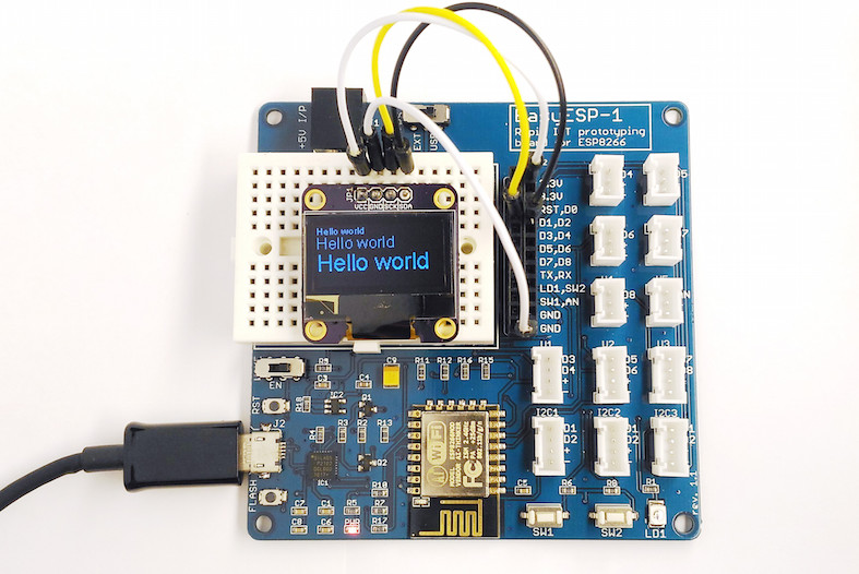
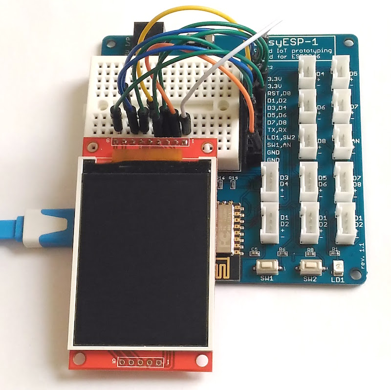
![Wiring OLED pins to the EasyESP-1 board]()
Wiring OLED pins to the EasyESP-1 board
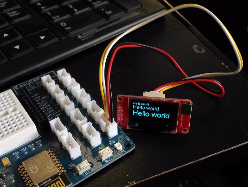
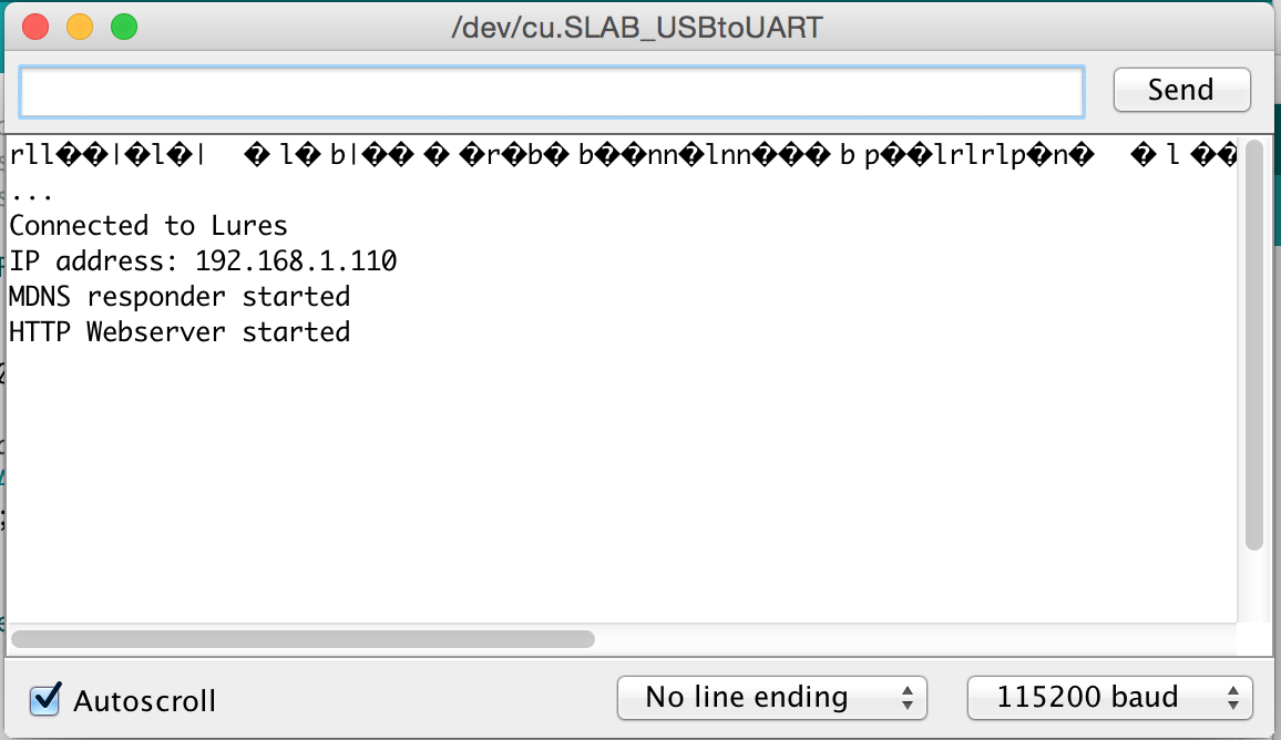
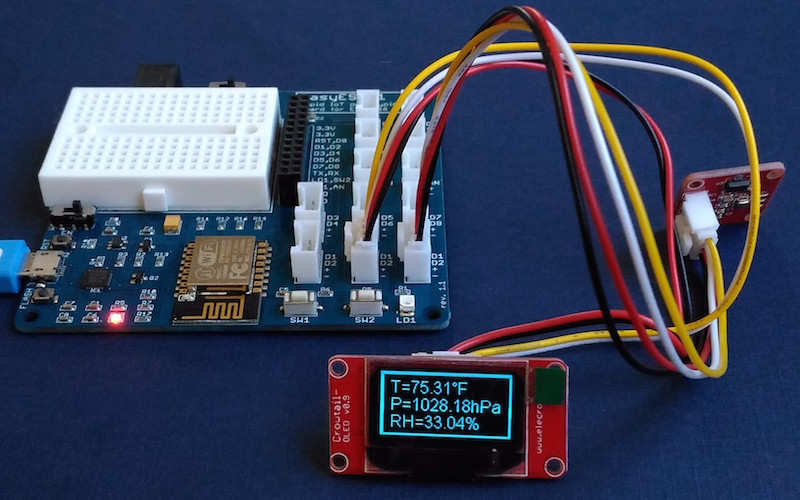
If you would like to use a grove OLED module, it can be connected to one of the I2C port on the EasyESP-1 board, as shown below.
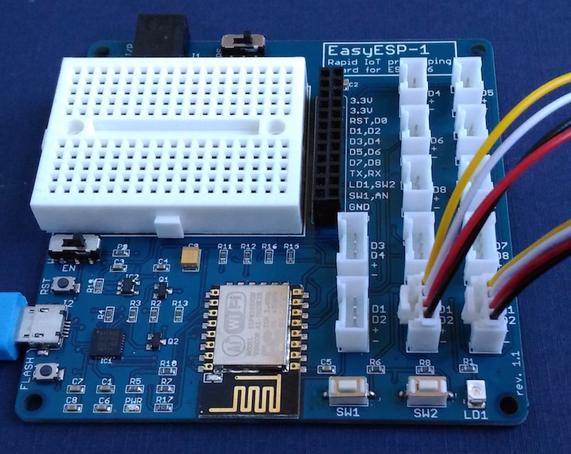
![Connecting a grove OLED]()
Connecting a grove OLED to I2C connector on the EasyESP-1 board
Software
There are several libraries available to support the SSD1036-based OLEDs for Arduino platform. For ESP8266, I would suggest to use one written by Daniel Eichhorn from squix. It supports both I2C and SPI versions of SSD1306 based 128×64 pixel OLED displays on the Arduino/ESP8266 platform. The library is very versatile and supports drawing pixels, lines, rectangles, and text of different font sizes. You can download this from the following github link.
https://github.com/squix78/esp8266-oled-ssd1306
Installation and setup of an external user library to Arduino IDE is easy. First, download the zipped library folder to your machine. Then unzip it and move the unzipped library folder to your Documents/Arduino/libraries/ location. You need to restart the Arduino IDE in order to use it in your new application.
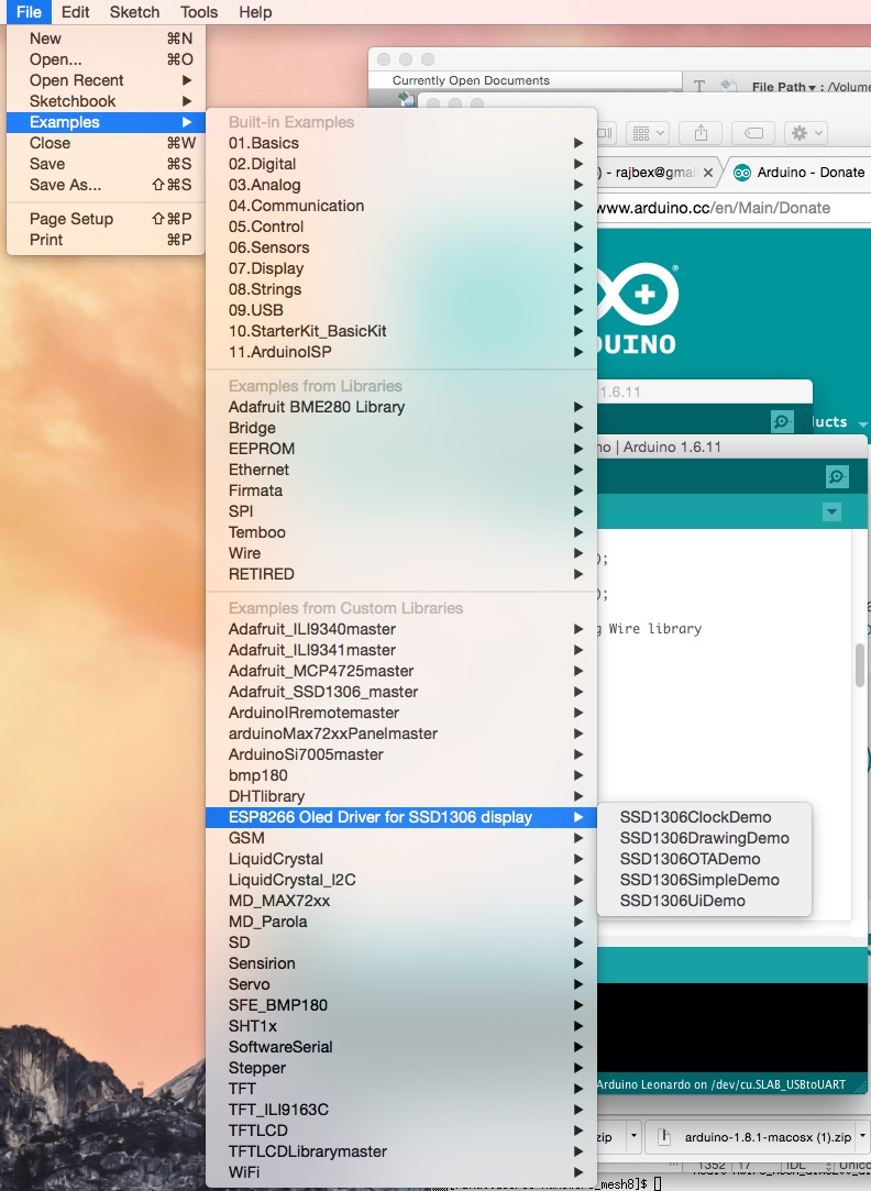
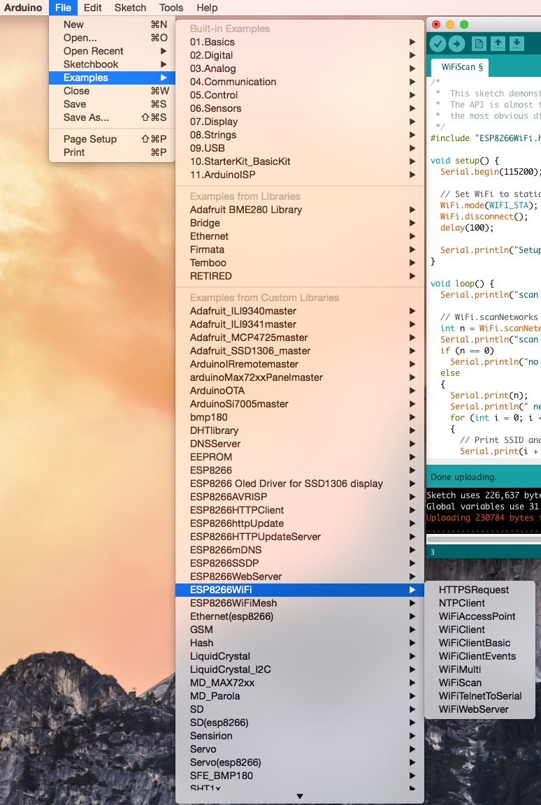
After installing the OLED library, it’s time to try some built-in examples that come with the library. Open File->Examples->ESP8266 Oled Driver for SSD1306 display-> SSD1306SimpleDemo.
![fgf]()
Testing OLED examples
The example programs are configured for I2C version of SSD1306 OLED by default. So, the only thing that you need to modify in the example code is to assign the correct ESP8266 I/O pins for I2C communication. Note that the EasyESP-1 I2C ports use D2 for SDA and D1 for SCL. So find the following I2C initialization statement in the code and make the changes as
// Initialize the OLED display using Wire library
SSD1306 display(0x3c, D2, D1);
Next, compile the program and upload it to the EasyESP-1 board.
Output
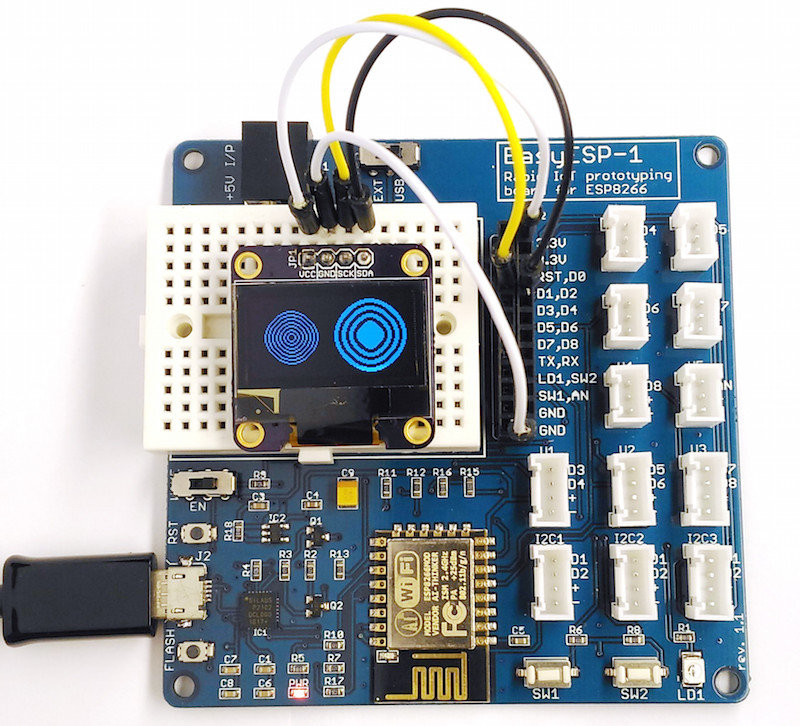
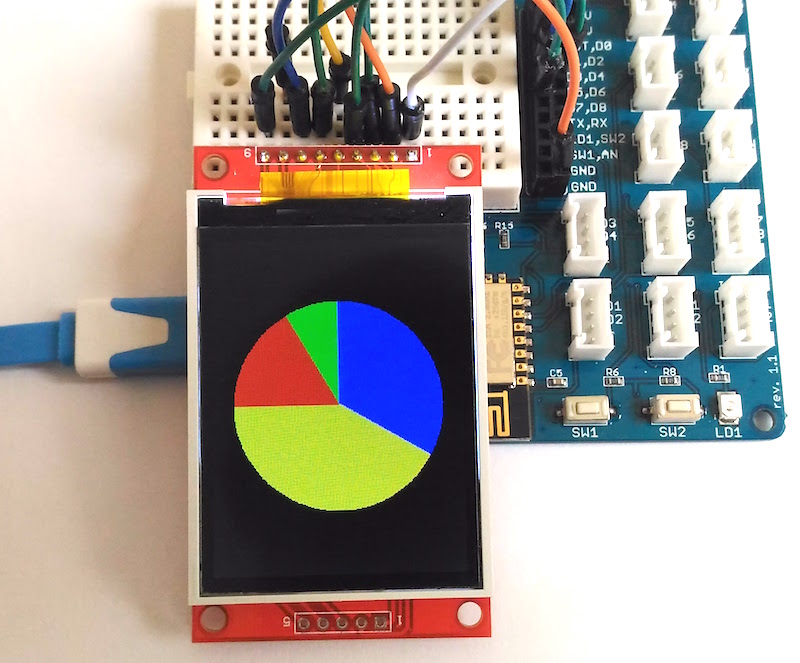
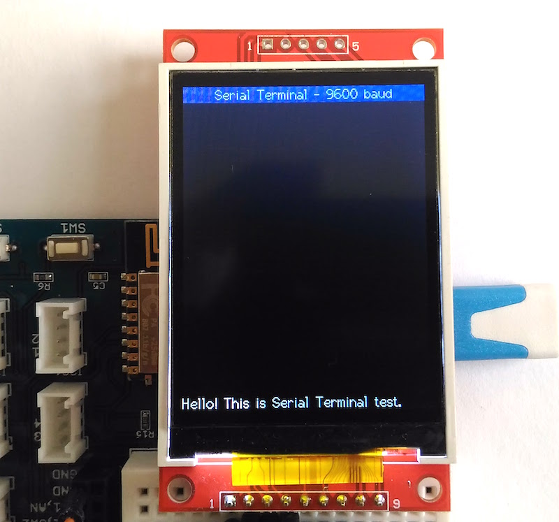
The SSD1306SimpleDemo example cycles through all the basic features of the OLED library, like drawing pixels, rectangle, circles, texts, WiFi logo, etc.
![Drawing concentric circles]()
Drawing concentric circles
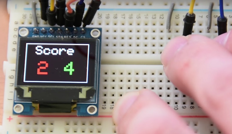
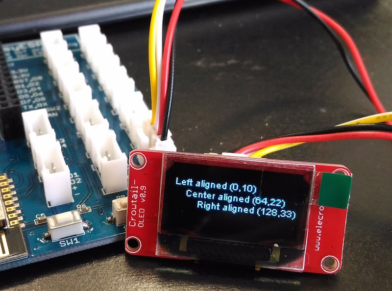
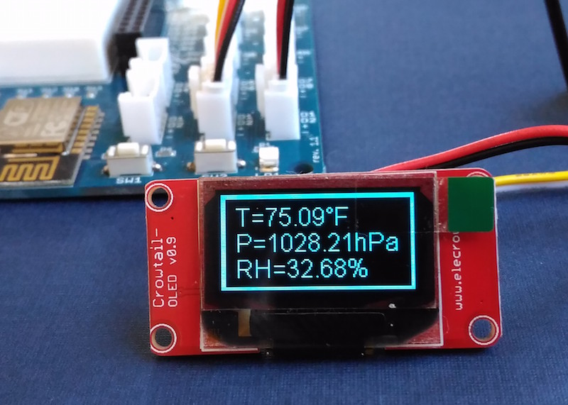
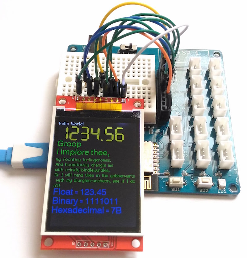
![OLED text output]()
OLED text output
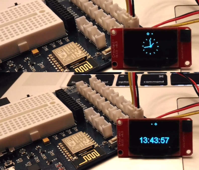
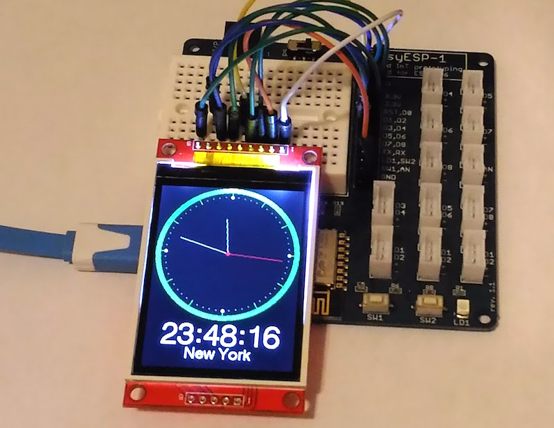
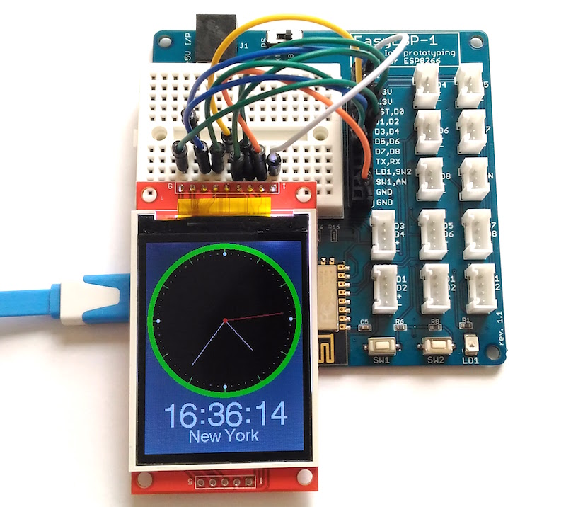
You can also try running other examples in Daniel’s OLED library. There is one called SSD1306ClockDemo that displays an analog and digital clock on the LED screen. For this example, you will need to install the Arduino Time library.
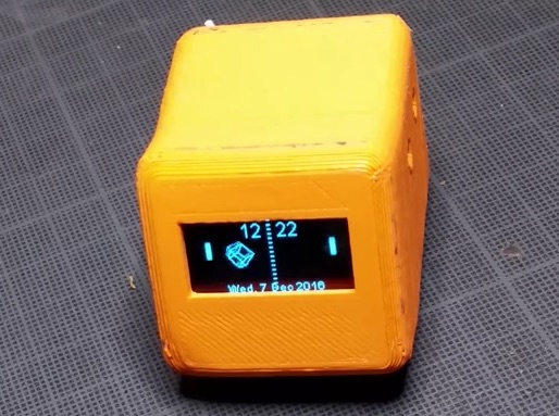
![Clock example]()
Clock example
More tutorials
The post Tutorial 3: Connecting an OLED display to ESP8266 appeared first on Embedded Lab.
![]()