Tired of hand-mixing ingredients for your favorite cocktail drink? This Arduino-powered automatic drink mixer can get your favorite 6-shooter recipe ready with a push of a button. You need to select your drink from the list shown on an LCD screen, push the button, and it will pour the drink in your glass. It uses 7 solenoid valves and a single pump to access drink from 6 containers.
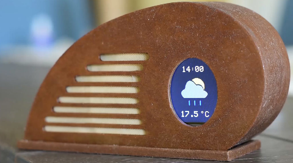
Nick Koumaris from educ8s.tv has posted a new project of building a ESP8266-based weather forecast display using Wemos D1 mini board and a 1.8” Color TFT screen. Nick also shares the design files for his artistic 3d printed enclosure for this project. The ESP8266 on board Wemos D1 mini connects to the internet to retrieve the weather forecast for a particular location and displays it on the TFT screen.
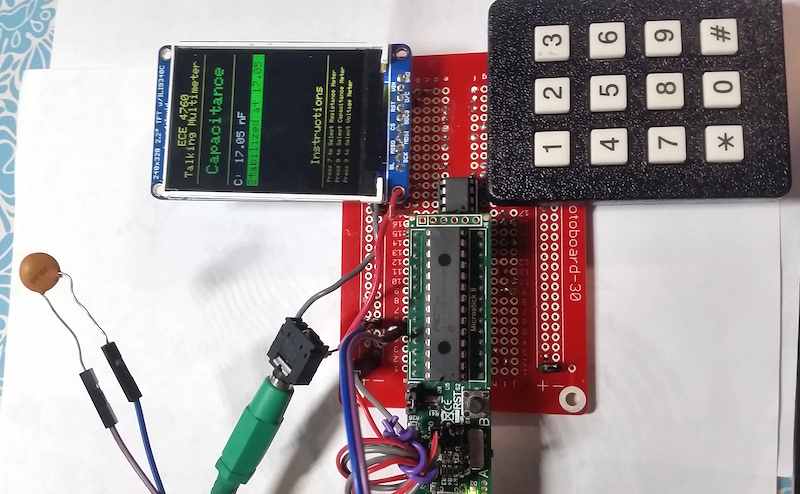
Rachel Dipirro and Jonathan Lo (students of Cornell) built a talking multimeter as their final project for the 2016 Fall ECE 4760 (“Designing with Microcontrollers”) course. Their talking multimeter is powered with the PIC32MX250F128B microcontroller, and it can speak the measured readings while operating as a volt-, ohm-, and capacitance-meter. It is aimed to provide the user these measurements without turning away from the circuit currently being worked on.
The speaking measurement system will provides an auditory alternative to a visual meter. Our system consists of a TFT LCD to display the reading, a keypad to read user input about the mode of the system, and speakers to hear the readings of both the keypad and the measurements. Key presses on the keyboard determine if the multimeter is used a voltmeter, an ohmeter, or a capacitance meter. Additional circuitry and the functionality on the PIC32MX250F128B is used to map the voltages to ranges acceptable for the MCU and to calculate the parameter values. Capacitance values can be measured between 1pF and 100nF. Resistance values can be measured between 0 and 50kΩ. Voltage values can be measured up to 10V and mapped down appropriately for the MCU using a voltage divider.
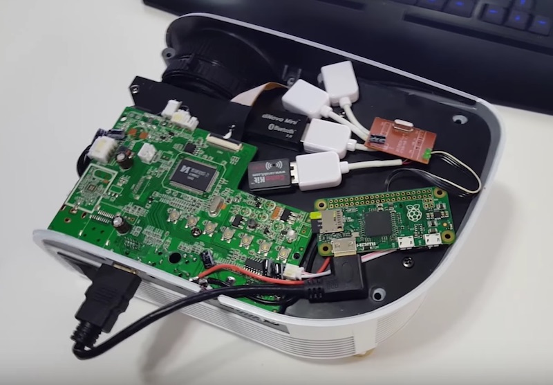
Like smart TVs, smart projectors also features built-in Wifi connectivity and support media streaming from services like Netflix, YouTube, Hulu, Amazon, and so on. A recent video from NovaSpirit (posted below) illustrates how to convert a cheap $70 standard projector into a smart projector by adding a Raspberry Pi Zero.
An USB hub is hardwired to the Pi Zero so that you can use an Wifi dongle (for internet connectivity) and an USB keyboard. The Pi Zero board derives power from the projector circuit board.
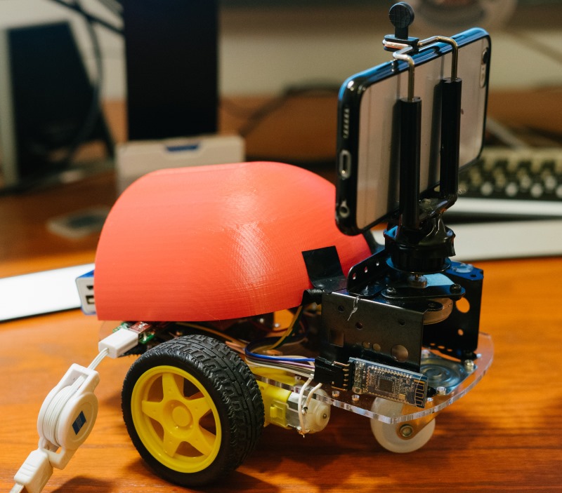
Motion-controlled autonomous camera robots are great for capturing moving time-lapse. Sacheth, Ope, and Jason (three ECE students at Cornell) built an iPhone controlled moving robot with a mounted camera to serve the same purpose. The position of the camera can be controlled as well through the iPhone App. Users can also pre-program it with certain motions with time intervals to capture a moving time-lapse of a landscape.
The brain of their camera robot is the PIC32MX250F128B microcontroller that receives commands from the iPhone App over Bluetooth. Two DC motors are used to drive the camera robot, while a unipolar stepper motor controls the camera rotation. See the demo video below:
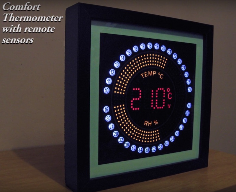
Building a thermometer is a very popular project among beginner hobbyists. This comfort thermometer display built with 517 LEDs and four microcontrollers is a beautiful piece of art work with a very impressive and colorful display.
The bargraph LEDs are current sinked with LM3914 LED display drivers, and current sourced via the PIC16F886 and transistors. The information from the temperature sensor (LM35) and humidity sensor (HIH-4030) is wirelessly transmitted once a minute to the main auto-dimming display which cycles through every 19 secs.
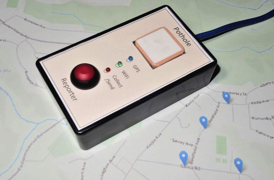
Potholes are one of the most common paving problems. They can not only damage vehicles but are also considered a serious road hazard. mchampio has posted an Instructables about building a NodeMCU based pothole reporter that records the locations of the potholes encountered during driving and later notifies the concerned authority. The location of the potholes are captured using a GPS module. Every time a pothole is encountered, the driver needs to press a push button to record its location. It can be further automated by installing an accelerometer for detecting the potholes.
Here is a very comprehensive Instructable from fgebhart about building a smart IoT alarm clock using Pi Zero that has some really nice features such as text-to-speech synthesizer, multiple wake-up sounds (such as MP3 songs, your favorite internet radio station, or news channel), alphanumeric LED segment displays with auto intensity adjustment, and more.
play latest news as podcast (independent to the alarm time)
set alarm via smartphone or any other computer
running apache2 server
automatic display brightness adjustment
audio amplifier volume control
3D-printalbe case
case built-in tactile switch
alphanumeric display shows text
3W speaker definitely wakes you up
… whatever you want to add …
In order to complete this project you need to set up a Raspberry Pi running Raspbian (Lite), the Debian version of Raspberry Pi. Sure you might use different Raspberry Pis and a different OS, but therefore you might need to modify your system somewhat. For example if you want to use Raspberry Pi 3 you don’t have to buy and use an additional WiFi-stick, might just use the on-board audio output, but might not be able to use the given 3D-printable case. So by changing some parts of this project you got to keep in mind that this instruction is based on using Raspberry Pi Zero.
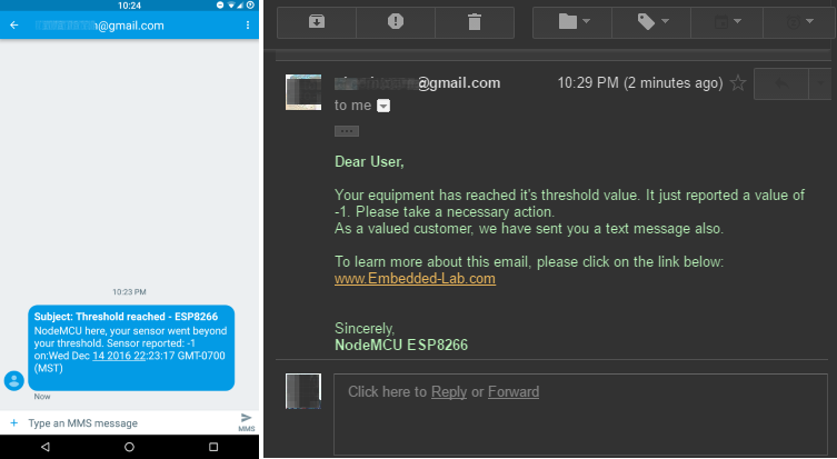
Earlier we looked at a method of programming ESP8266 to send sensor data directly to Google Sheets without using any third party modules. Now, we will expand that a little bit and learn to send an email as well as a text message (SMS) using ESP8266. In this demo, we will configure our ESP8266 to send an email and a text message when the value of a variable (which could be a sensor output, or any other physical quantity) goes beyond a threshold limit.
This is not entirely a new topic as there are similar tutorials available online to show how to do this. This article particularly focusses on just using the ESP8266 and Google environment to send email or a text message.
To understand the concept, all we need is an ESP8266 module and a power supply for it, usually a USB cable. I am using a NodeMCU board for convenience. We do not need any sensors or other things. For illustration of the method, we will just generate a random number between certain intervals, and if the number goes beyond what we have set for threshold limit, we would like to receive an email and/or a text message.
Prepare a Google Sheets:
Just like in pushing data to ESP8266 to Google Sheets, we will create a new Google Sheet in a Google Drive. So, let’s do the following:
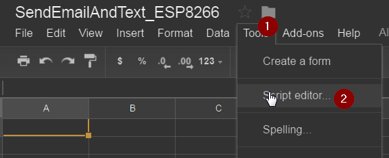
1) Open up your Google Drive in a web browser and create a Google Sheets. You can call this file whatever you like. I called it ‘SendEmailAndText_ESP8266’.
2) From the Google Sheets that you just created, go to Tools > Script editor…
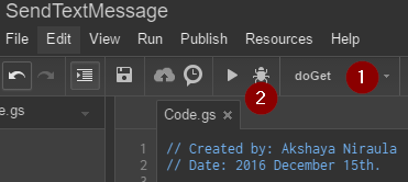
3) Give a name to the Script editor main file in the toolbar (whatever you like).
4) Paste the following code to the Code.gs file (assuming you haven’t change the default file name). Again, this filename doesn’t matter either.
Google Scripts Code:
// Created by: Akshaya Niraula// Date: 2016 December 15th.// Steps are valid as of 2016 December 15th.// 0) From Google spreadsheet, Tools > Script Editor...// 1) Write your code// 2) Save and give a meaningful name// 3) Run and make sure "doGet" is selected// You can set a method from Run menu// 4) When you run for the first time, it will ask // for the permission. You must allow it.// Make sure everything is working as it should.// 5) From Publish menu > Deploy as Web App...// Select a new version every time it's published// Type comments next to the version// Execute as: "Me (your email address)"// MUST: Select "Anyone, even anonymous" on "Who has access to this script"// For the first time it will give you some prompt, accept it.// You will need the given information (url) later. This doesn't change, ever!var number ="8001239999";// your phone number var domain ="tmomail.net";// You may find your domain for you carrier at: http://www.emailtextmessages.com/var toEmail ="YourOrFriendsEmail@gmail.com";function doGet(e){
Logger.log("--- doGet ---");// for debuggingif(e ==null){e={}; e.parameters={value:"-1"};}try{// get the values from parameters to local varvar value = e.parameters.value;var phoneEmail = number +"@"+ domain;// Send Text Message (SMS)
send_Email(phoneEmail,"NodeMCU here, your sensor went beyond your threshold. Sensor reported: "+ value +" on:"+newDate());// Send Emailvar message ="<b>Dear User,</b>
Your equipment has reached it's threshold value. It just reported a value of "+ value +". Please take a necessary action.
";
message +="As a valued customer, we have sent you a text message also.
";
message +="To learn more about this email, please click on the link below:
";
message +="<a href="http://www.embedded-lab.com/" target="new">www.Embedded-Lab.com</a>";
message += "Sincerely,<b>NodeMCU ESP8266</b>";
send_Email(toEmail, message)
return ContentService.createTextOutput("Things went successfully.");
}
catch(error) {
Logger.log(JSON.stringify(error));
return ContentService.createTextOutput("oops...." + error.message
+ "\n" + new Date()
+ "\nnumber:" + number +
+ "\ndomain:" + domain);
}
}
function send_Email(address, message){
MailApp.sendEmail({
"to": address,
"subject": "Threshold reached - ESP8266",
"htmlBody": message
});
Logger.log("send_textMessage:" + "Email sent to:" + address);
}
As shown in the image below, select doGet and click on bug icon to debug your code. If you followed the steps properly, you should have received a text message and an email from you gmail account.
Please note Google will need your permissions to send email on your behalf so when Google asks for the permission, you must provide it.
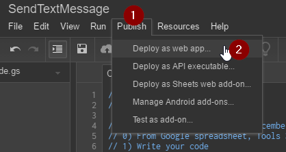
If you didn’t receive a text message and/or an email, please double check your steps. If you did receive then let’s publish our work so that we can get a URL which we can use in NodeMCU. To publish, click on Publish > Deploy as web app…
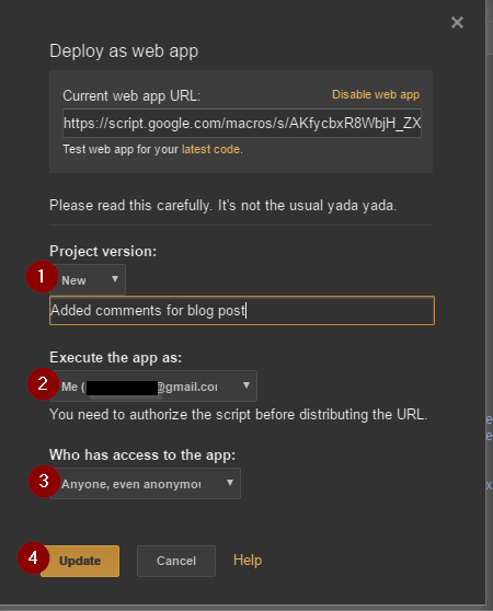
When you click on Update or Publish, you will see a box as shown below. From this box, copy the given address. I usually save this address back into Google Script for future use. We will need this address in NodeMCU/ESP8266 code.
Note: we will call the text between /s/ and /exec as GScriptID. This information is required in NodeMCU code.
Grab the URL from above box and append the “?value=-1” to it, it will look something like this:
https://script.google.com/macros/s/—YourGScriptIDGoesHere—/exec?value=-1. Now paste this URL to your browser’s address and press enter. In a few seconds you should receive an email and a text message.
if(!flag){ Serial.print(“Could not connect to server: “); Serial.println(host); Serial.println(“Exiting…”); Serial.flush(); return; }
// Data will still be pushed even certification don’t match. if(client.verify(fingerprint,host)){ Serial.println(“Certificate match.”); }else{ Serial.println(“Certificate mis-match”); } }
// This is the main method where data gets pushed to the Google sheet voidsendValueToGoogle(Stringvalue){ if(!client.connected()){ Serial.println(“Connecting to client again…”); client.connect(host,httpsPort); } StringurlFinal=url+“value=”+value; client.printRedir(urlFinal,host,googleRedirHost); }
// Continue pushing data at a given interval voidloop(){
// Here you will have your main code // To demonstrate the concept we are generating a random number longrandomValue=random(10,20);
// Our lower threshold is 12 and upper threshold is 18 // when given vlaue goes below lower or above upper the threshold // we would like to send information to GAS for email and text message if(randomValue<12||randomValue>18){ Serial.println(“Random value outside the threshold: “+String(randomValue)); sendValueToGoogle(String(randomValue)); }
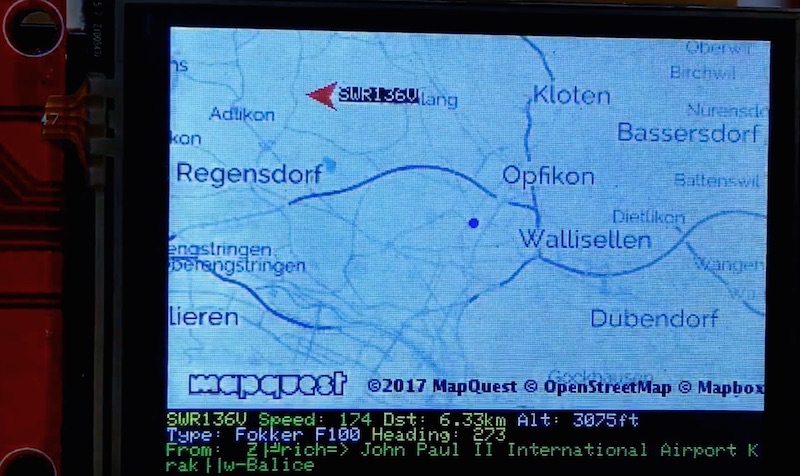
Daniel Eichhorn recently upgraded his original text version of Plane Spotter project with a colorful TFT screen displaying a map along with airplanes on it. The project requires an the ESP8266 Wifi module (Wemos D1 Mini in this case) and an ILI9341/ XPT2046 TFT display with touch screen.
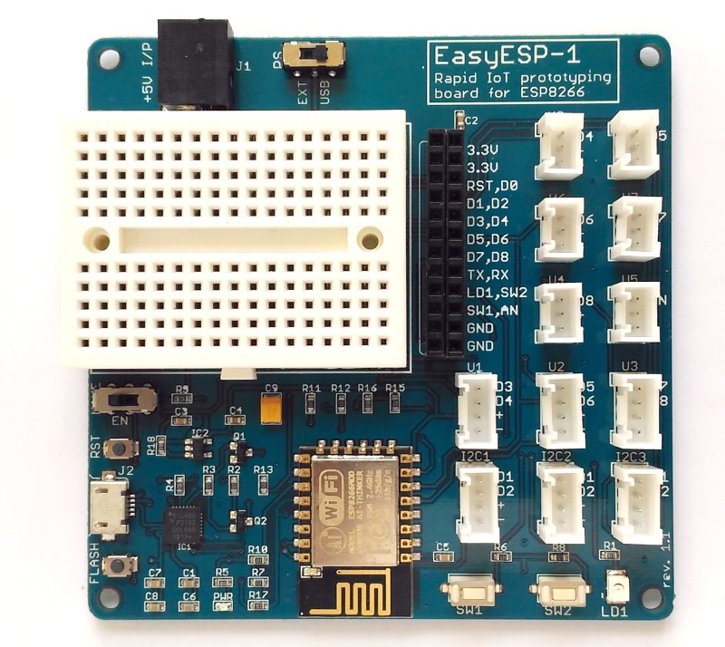
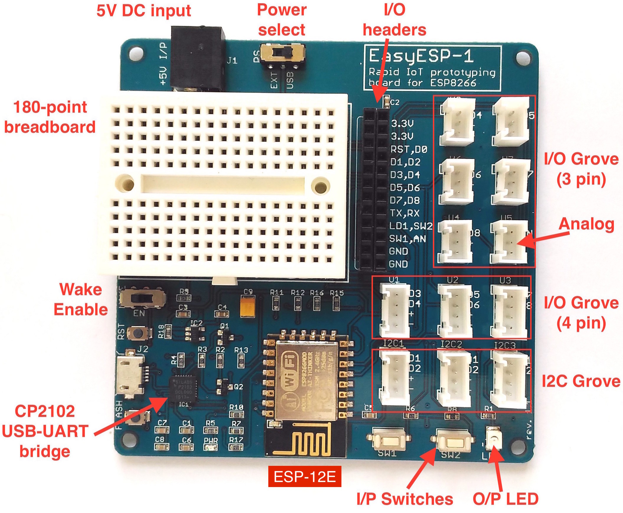
EasyESP-1 is a rapid prototyping development board for the low-cost, WiFi-enabled ESP8266 microcontroller. With an onboard USB-to-Serial converter pre-installed, EasyESP-1 does not require any additional hardware to download your application firmware to the ESP8266 chip. The ESP module used in this development board is ESP-12E. All the I/O pins are broken out to 0.1” female headers for easy access, as well as to standard Grove connectors for connecting Grove sensors and other compatible modules. The 180-point breadboard further facilitates experimenting and testing of external circuits. You can buy EasyESP-1 from our Tindie Store. Non US buyers can also get it from Elecrow.
The ESP8266 module operates at 3.3V power supply. The EasyESP-1 derives the 3.3V power supply for the ESP12E module from the USB port or an external 5V DC input using the SPX3819 low-noise LDO voltage regulator. The maximum current capacity of the LDO is 500mA. There is a power select (PS) slide switch (see Fig. 2) to switch between the USB and the external 5V power supply options. During programming, the EasyESP board is connected to the PC’s USB port, so it is convenient to use the USB power supply. The PS switch must be in the USB position in order to use the USB power source. If you need to use an external power supply for any reason, you will need a regulated +5V DC with minimum current rating of 500mA (1A recommended) and with a 2.1mm male output power plug. The external power supply plugs into the input DC barrel jack next to the PS switch. Note that the PS switch must slide to the EXT position in this case.
Note: Remember, the external DC input should be a regulated +5V.
CP2102 USB-UART bridge
EasyESP-1 uses Silicon Labs’ CP2102 USB to serial bridge device on board for uploading user applications to the ESP module. It also allows the users to use a serial terminal program (such as serial monitor on Arduino IDE) on a computer for debugging. Drivers for this USB-UART bridge device can be downloaded from Silicon Labs website.
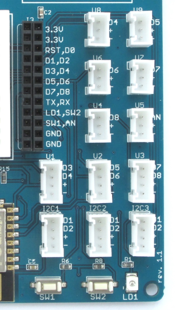
I/O peripherals
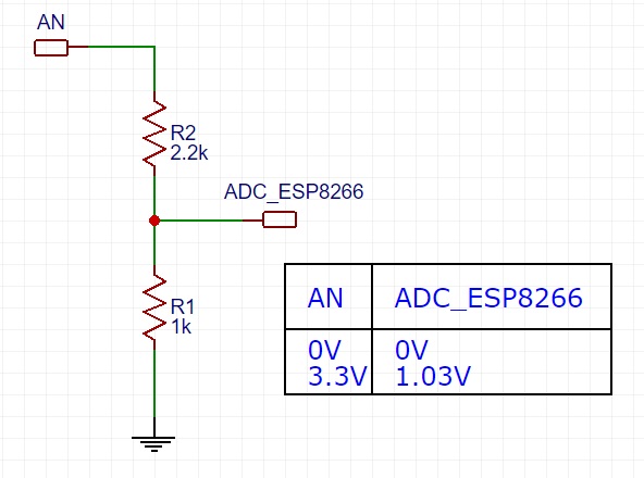
The I/O pins of ESP12E module are broken out to 0.1″ pitch female headers (J3), as well as to multiple grove connectors. The ESP12E I/O pins that are available on the board are RST, D0-D8, Tx, Rx, and analog input pin AN. The built-in ADC of ESP8266 has 10-bit resolution and can accept an input voltage ranging from 0 to 1.0V. In order to expand the range of input analog voltage to 3.3V, EasyESP-1 incorporates a simple 2-resistor voltage divider network as shown in Fig. 3.
A resistor divider network increases the range of ADC input to 3.3V.
The two user tact switches (SW1 and SW2) and one user LED (LD1) are also accessible through female headers (J3). The tact switches output are pulled up “High” during default conditions. When they are pressed, the corresponding J3 pins (SW1 and SW2) turn “Low”. Similarly, LD1 is configured as active high, which means when the LD1 pin of J3 is connected to logic “High”, the LD1 LED turns on. All ESP12E I/O pins, user tact switches and LED, and power supply pins are arranged in a 2×12 header (J3). The AN pin is also accessible through U5 grove connector. In ESP8266, I2C is implemented by bit-banging and as such any two I/O pins can be configured as I2C bus. However, to make it easier for the users, the EasyESP-1 board provides three I2C grove connectors (I2C1, I2C2, and I2C3) that are hard-wired to D1 (SCK) and D2 (SDA) pins. A close-up picture of just the I/O section of EasyESp-1 is given in Fig. 4 .
A 2×12 female header (J3) and grove connectors provide access to the ESP12E I/O pins and the user switches and LED.
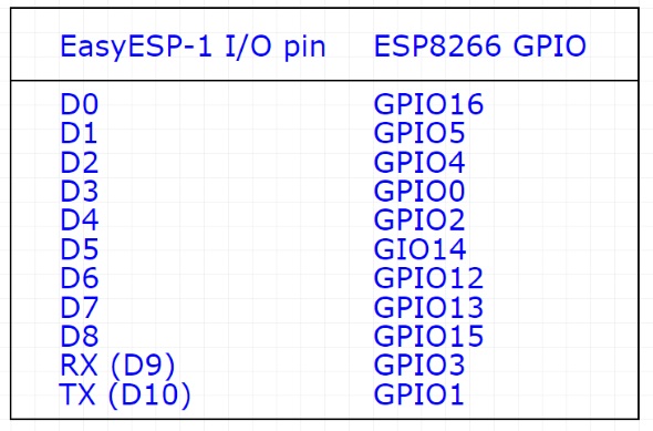
It should be noted that EasyESP-1 uses the same I/O indexing as used by NodeMCU. This does not match with internal GPIO indexing. For example, pin D1 is actually mapped to internal GPIO5. If you use Arduino IDE for programming EasyESP-1, you can access this pin in both ways. For instance, digitalWrite(D1, LOW) and digitalWrite(5, LOW) will both do the same thing, writes out logic ‘low’ to D1 pin. Following diagram describes the pin mapping between EasyESP-1 Dx and ESP8266 internal GPIOs. Note that TX and RX pins can also be called for normal I/O operation by addressing them as D10 (GPIO1) and D9 (GPIO3), respectively.
EasyESP-1 I/O pin indexing vs ESP8266 internal GPIOs
Wake Enable switch
For low-power applications, ESP8266 can be put into deep sleep mode during idle conditions. In order for the ESP8266 to automatically wake up from sleep mode after a certain interval, the XPD/D0 pin (which is also GPIO16) must be tied to the ESP8266’s reset line. In EasyESp-1 board, this can be easily done by sliding the Wake Enable switch to EN position.
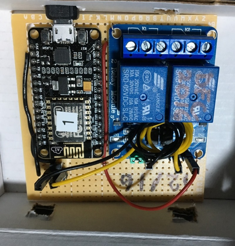
This ESP8266 controlled garage door opener activates the garage switch via commands send over an web browser. In addition, it also records the activities to a Google Sheet using the IFTTT.com services.
There seems to be an unstoppable drive in the hacker DIY community for web based garage door openers and we were compelled to respond. The garage door opener we have opens/shuts from a push button switch that basically creates a short to connect two terminals on the garage door opening unit. That allows easy implementation because all that is required is a ESP8266 controlled relay wired across those two terminals to create a switch closure.
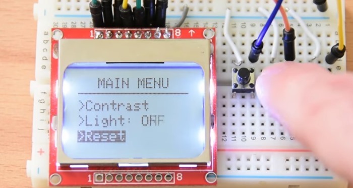
An interactive menu driven LCD user interface (UI) is really useful in embedded applications that require setting up parameters for operation. This YouTube tutorial demonstrates how to manage a simple menu driven UI on a Nokia 5110 LCD for Arduino applications.
This is the project we are going to build. In the display a simple menu appears, and with the help of three buttons I can navigate up, or down and select a menu item. Let’s select the first option. As you can see a new a UI screen is displayed and by pressing the up and down buttons we can change the contrast of the display. If we press the middle button again, we go back to the main UI screen. If we now select the second menu item and press the middle button we can turn the backlight of the display on or off. Lastly if we navigate to the last menu item we can reset the settings for the display to the default values. Of course this is just a demonstration project, you can modify it to build your own more complex menus if you wish. Let’s now see how to build this project.
One of the simplest way to program the ESP8266 chip on board EasyESP-1 is using the Arduino IDE. Following steps describe how to enable the ESP8266 support in the Arduino environment.
Step 1 : Install Arduino IDE
The first step toward setting up the Arduino platform for programming EasyESP-1 is to download and install the Arduino IDE. Go to the Arduino website and download Arduino IDE 1.6.11.
Step 2: Install ESP8266 core package
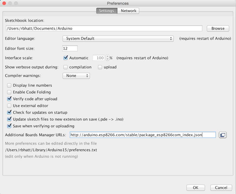
Next step is to install the ESP8266 core for Arduino IDE. It is an add-on that allows to write sketches for ESP8266 using the Arduino IDE and its libraries. The easiest way to install the ESP8266 core is by typing in http://arduino.esp8266.com/stable/package_esp8266com_index.json
into Additional Board Manager URLs field in the Arduino-> Preferences window (see figure below).
Adding ESP8266 support to Arduino IDE using Preferences window
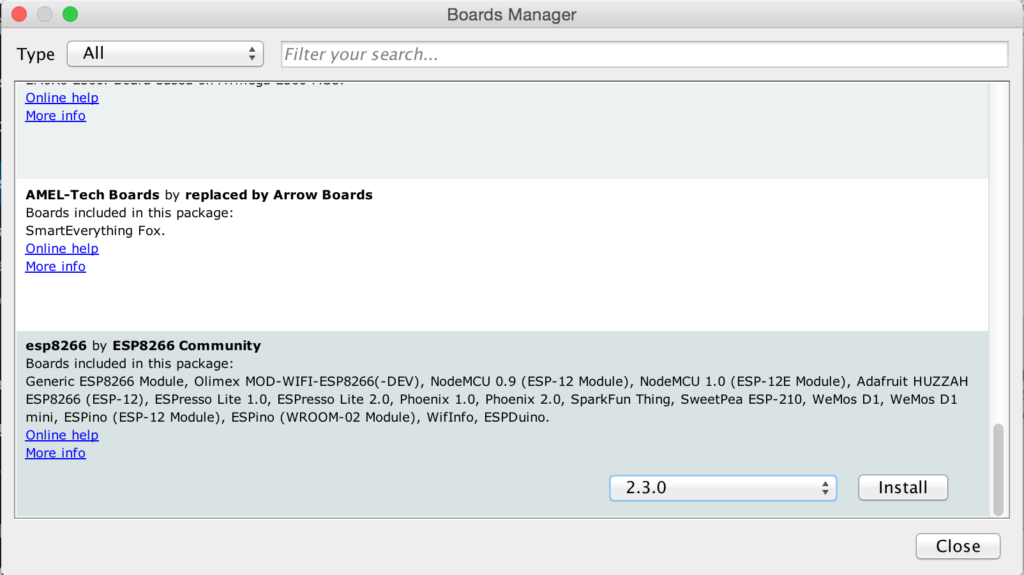
Click OK and then go to Boards Manager and install the ESP8266 core. It appears at the end of the list as esp8266 by ESP8266 Community (see figure below). Select 2.3.0 version from the dropdown list.
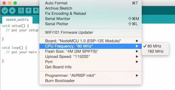
CPU clock should be set to 80 MHz and Upload Speed to 115200
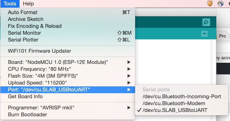
Step 4: COM Port selection
Finally, you need to select the right COM port that your EasyESP board is connected to. Obviously, you need to connect the EasyESP-1 to the computer through a USB cable. If the driver for SiLabs CP2102 USB-UART device is installed properly, it will show up in the Arduino IDE Tools->Port list as a new serial port. In Windows machines it shows up as a new COMx port. The following figure shows how it appears on a MAC computer. You should select the matching serial port for the CP2102 device on EasyESP from the Port list.
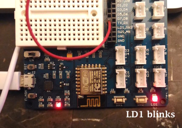
After setting up the Arduino IDE to enable support for ESP8266, it’s time to write your first code for EasyESP-1 board. We will start with the classic hello world! example of electronics, a flashing LED. This is the best example to start with any new hardware platform as it gives us an opportunity to verify that the required software tools/drivers are installed properly and ready to rock.
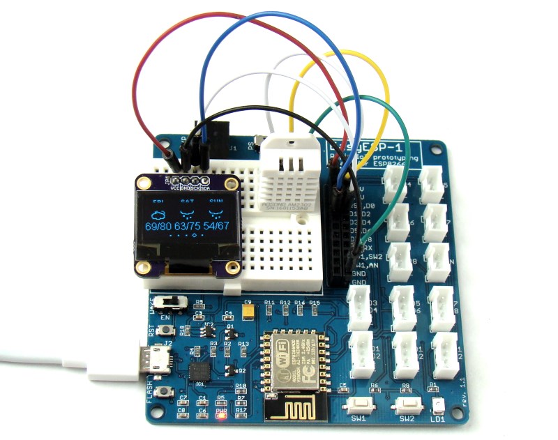
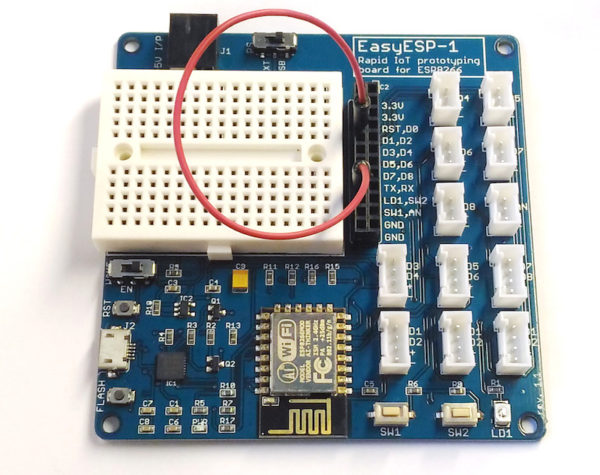
Hardware Setup
In this example, we will connect the LD1 and D1 pins of J3 header together with a jumper wire as shown below. This will connect the LD1 LED near the bottom right corner of EasyESP-1 to the D1 I/O pin (or GPIO5) of ESP8266.
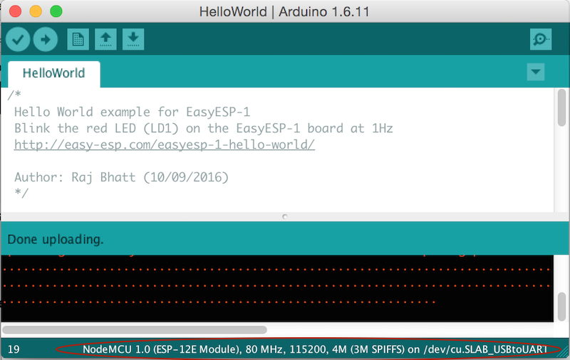
Open a new window on Arduino IDE and select appropriate options for Boards, Serial Port, CPU frequency, and Upload speed. You need to choose NodeMCU 1.0 (ESP-12E Module) from Board menu, set CPU frequency to 80 MHz, Upload Speed to 115200, and match Serial Port to the one that your EasyESP-1 is connected to. Check out my previous tutorial “Getting started with EasyESP-1 using Arduino IDE” for more details on this. Your selected options are shown in the bottom tab of the Arduino IDE, make sure they match with the ones shown below.
As I described in the EasyESP-1 Introduction, EasyESP-1 uses the same I/O indexing as used by NodeMCU. This does not match with internal GPIO indexing. For example, pin D1 is actually mapped to internal GPIO5. In Arduino IDE, you can access this pin in both ways. For example, digitalWrite(D1, LOW) and digitalWrite(5, LOW) will both do the same thing, writes out logic ‘low’ to D1 pin. Next, copy the following code and paste it into your empty program window. The program is written to blink the LD1 LED at a rate of 1Hz. Save the code, verify it, and upload it to EasyESP-1 board in the same way as you do for Arduino.
/*
Hello World example for EasyESP-1
Blink the red LED (LD1) on the EasyESP-1 board at 1Hz
*/#define LD1 D1 // Define LD1 as D1 I/O pin// Alternatively, you can also define it as GPIO5//#define LD1 5void setup(){
pinMode(LD1, OUTPUT);// Initialize LD1 as output}void loop(){
digitalWrite(LD1, LOW);// Turn ON LD1
delay(500);// Wait for 0.5 sec
digitalWrite(LD1, HIGH);// Turn it off
delay(500);// Wait for 0.5 sec}
Output
If everything worked perfectly, you would see LD1 flashing at 1 Hz and with 50% duty cycle (i.e. on and off time are both 0.5 sec).
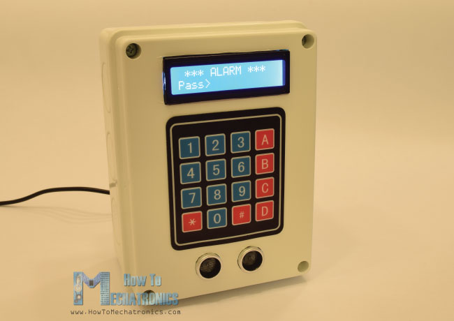
Dejan Nedelkovski from HowToMechatronics illustrates the use of HC-SR04 ultrasonic distance sensor in object detection, and its application for making a very basic password-protected Arduino-based security/alarm system. The project uses an Arduino board, character LCD display, 4×4 keypad,HC-SR04 ultrasonic sensor and buzzer.
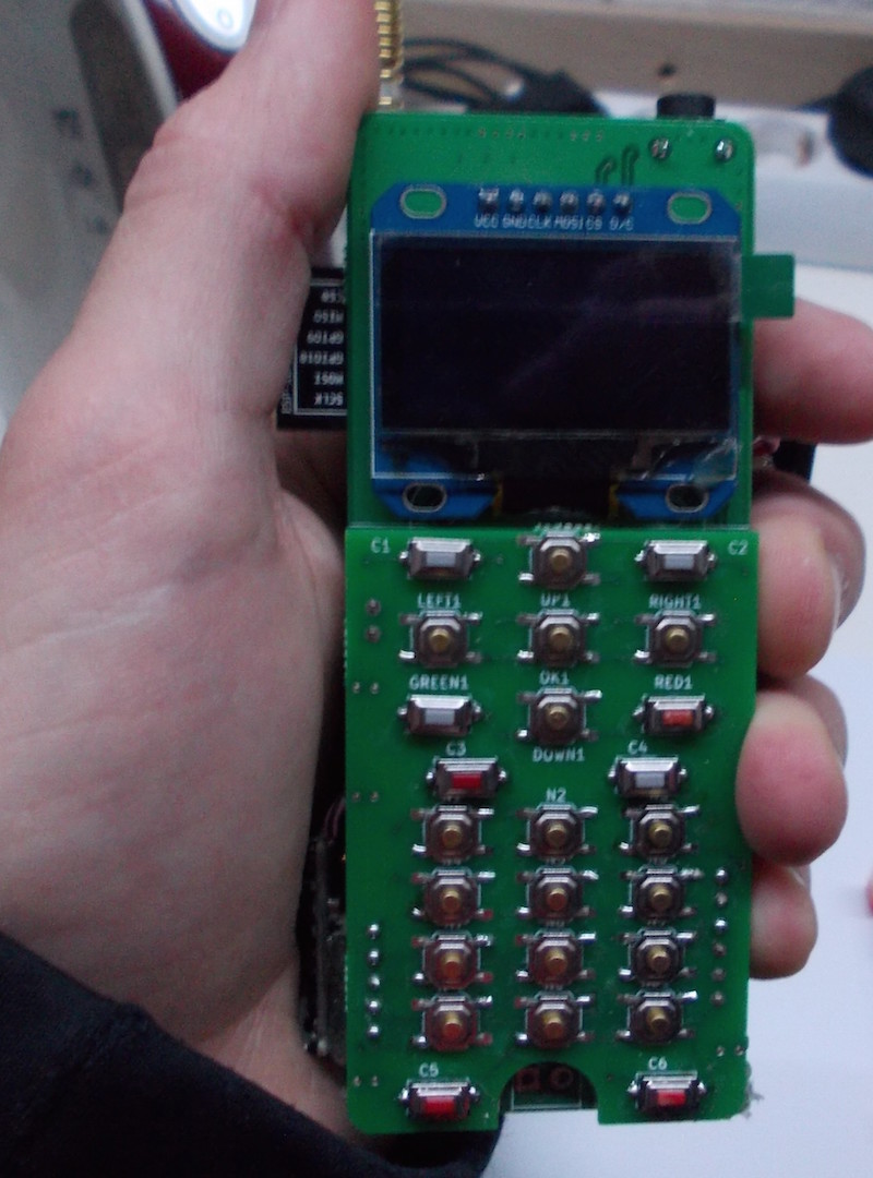
We have seen Arduino-powered cellphones before. Arsenijs introduces ZeroPhone– a Raspberry Pi Zero powered DIY mobile phone that costs less than $50 in parts. It is mostly open-source and linux-powered. It supports voice calls, texting, and basic apps like alarm clock, calendar, calculator, web browser, music player, etc.
Calling and SMS – this is the first functionality to be implemented, and will be considered crucial in the development.
All the basic apps – alarm clock, calendar, calculator, phonebook, file browser, web browser and music player.
Your own apps – SDK will be provided and it will be developer-friendly. The laand I’ll personally expect, if not at least aid with, social media apps – for a good start, since those are the apps people spend most time in.
Running Linux software – since it’s a computer after all, you can run ARM compatible (thus, almost all) Linux programs on it. A Raspberry Pi can give you a desktop with a monitor, keyboard and a mouse? This phone can, too! You like to use SSH, like me? It’s going to be available!
Pentesting – lots of fun, a nice hobby for many and well-paying work for some, this phone can do it too.
Security and privacy – one of the features that isn’t typically provided but can mean anything from something simply bringing peace of mind to a matter of life and death.
Experimenting – there’ll be a sensor port available for connecting anything you think could add useful functions to your phone. Want to wake up when the sun rises? Add a light sensor! An additional display for notifications? Easy, connect and write code! A Geiger counter? Can have it, too!
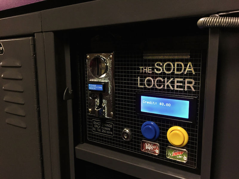
An Arduino-powered soda locker project posted by Mistablik on Instructables can easily fit into his locker and can supply two different kinds of pop. It features a coin acceptor that allows you to use nickels, dimes, and quarters for purchasing the soda.
Lockers just aren’t what they used to be. With so many schools moving to electronic devices for books, lockers become less of a space for your books, and more of a question of: “What am I going to do with this?”
What if you could use that space for your own vending machine? In this Instructable, I’ll tell you how I came up with the idea, how I designed it, how I solved a few problems along the way, and how it all turned out! So pop open a can of your favorite drink and come along!
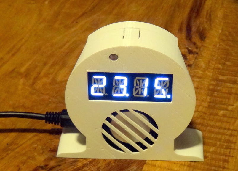
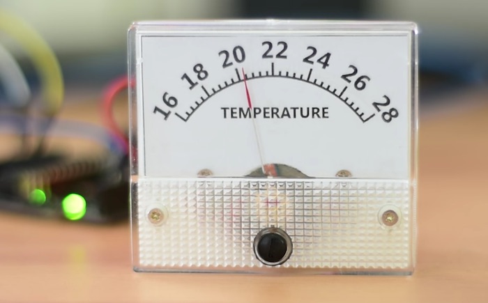
A new project tutorial from educ8s.tv is about making an Arduino based analog thermometer that uses an analog voltage panel meter for displaying temperature.
Today we are going to learn how to use this analog voltmeter with Arduino and make it show the temperature instead of the voltage. As you can see, in this modified voltmeter, we can see the temperature in degrees Celsius. The temperature is measured by this digital sensor, a DS18B20 and it is then displayed on the voltmeter. I really like analog dials like this one, because they give a vintage look to the projects. Let’s now see how to achieve that result.

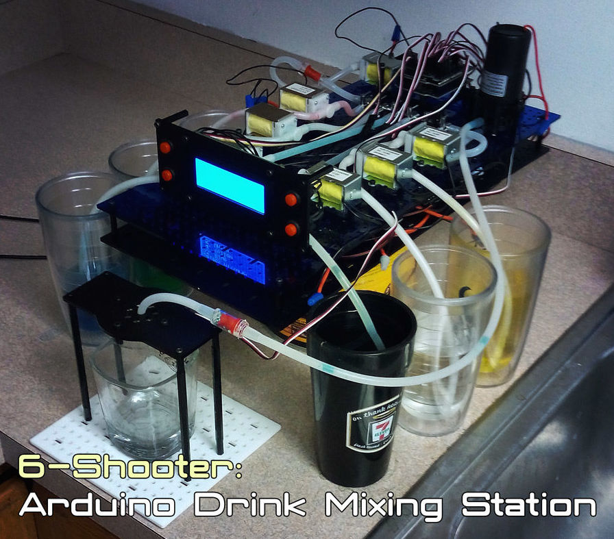
 Image may be NSFW.