The infrared (IR) communication technology, which existed long before WiFi and Bluetooth, is still a key component in implementing major components of a typical home automation system. For example, IR technology is still used in cordless headphones, for intrusion detection in home security systems, and in handheld remotes for controlling home entertainment systems (TV, DVD, soundbox, etc), air-conditioning units, and other household appliances. Because IR technology requires a line-of-sight between the transmitter and receiver units, it can only be used for connecting devices in short range, like in a same room. In one of my previous articles, I wrote about a simple IR remote control circuit based on the CD4017 decade counter IC. That was capable to switch on and off any home appliance hooked to it by using any TV/DVD remote. Today, I am going to show how to make an Arduino-based IR receiver for decoding the IR signals coming from a TV/DVD remote. Based on the decoded values corresponding to specific buttons on the remote, we will program the Arduino to control multiple relay switches.
![Controlling multiple relay switches using an IR remote]()
Controlling multiple relay switches using an IR remote
Circuit setup
The IR signal transmitted by a remote can be easily interfered by other nearby IR sources, such as heaters and incandescent lamps. Therefore, in order for the receiver to distinguish between the IR signals and all other sources of infrared noise, the transmitted IR signal is modulated. For modulation, a stable carrier frequency (typically 30–60 kHz) is required, with 38Khz being the most commonly used carrier frequency. Although there are several digital modulation techniques, most of the modern consumer electronics use Amplitude Shift Keying (ASK) for designing IR remote control units. In ASK, the amplitude of the carrier is varied in accordance with the digital input signal. Logic 1 is represented by a carrier signal of certain amplitude, while logic 0 is represented by changing the carrier amplitude to zero (or turning it off). You can find a lot more detail on IR modulation schemes in the following application notes:
IR remote control implementation … from TI
IR remote control techniques … from NXP
In this project, we will use IR signals coming from a TV remote for controlling multiple relay switches. In order to do that, we need an IR receiver circuit that would demodulate the IR signals transmitted by the TV remote. The demodulated digital output can be then directly interpreted by Arduino.
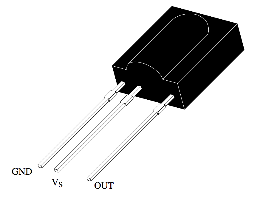
The receiving circuit for this project is built with the TSOP1740 IR receiver. The TSOP17XX series are miniaturized receivers with photo detector and preamplifier built in one package and are ready to use for infrared remote control systems. A bandpassfilter, an integrator stage and an automatic gain control are also used inside to suppress unwanted noises. The last two digits (XX) of its name represent the center frequency of the bandpass. Therefore, the TSOP1740 operates for a modulated IR signal of 40 KHz. For more details on TSOP17XX receiver, check the datasheet.
![TSOP17XX series IR receiver]()
TSOP17XX series IR receiver pin diagram
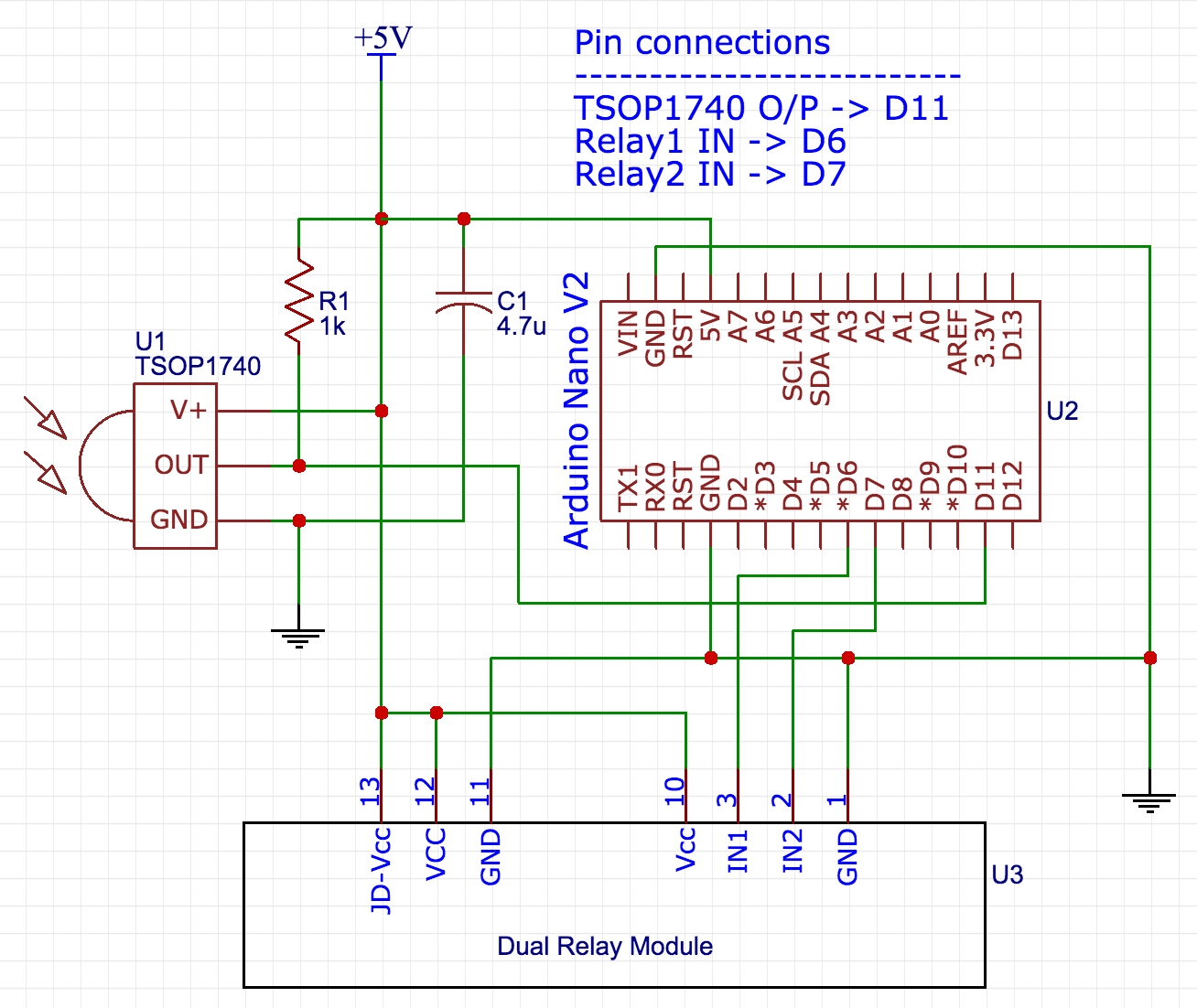
Shown below is the complete circuit setup required for this project. The demodulated output from TSOP17340 goes to Arduino pin D11. A dual relay control board is used in this demonstration. The control pins (IN1 and IN2) for the two relays are driven by D6 and D7 I/O pins of Arduino. The entire circuit operates at 5V.
![TSOP1740, dual relay module, and Arduino wiring]()
TSOP1740, dual relay module, and Arduino wiring
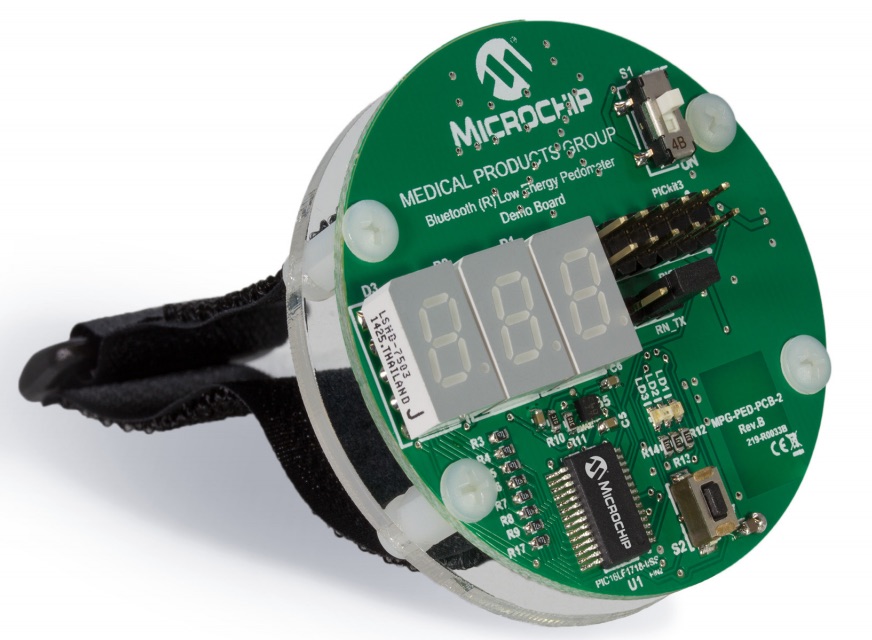
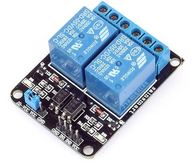
The relay board used in this project was purchased on Aliexpress for ~$3 and features optocouplers for electrical isolation between the input control pins and output relay driver circuit. The board looks like following.
![Dual channel relay board]()
Dual channel relay board
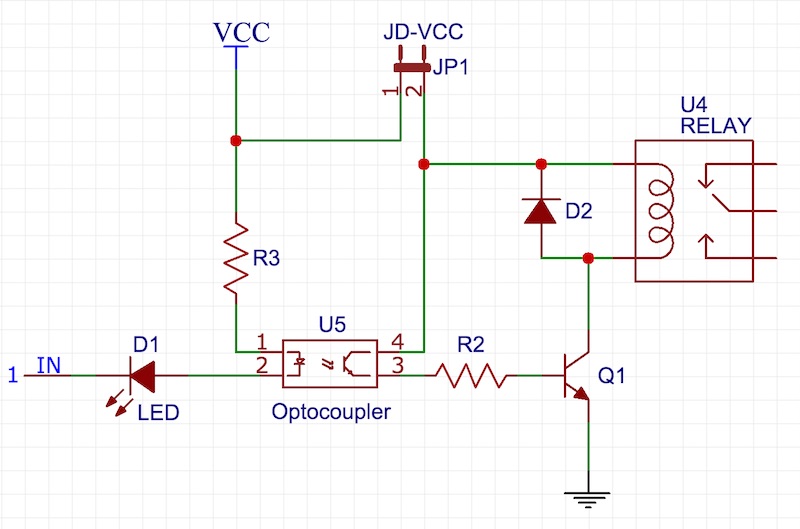
I have found that the onboard driver circuit for the two relay unite operates with active low inputs. That means, the IN pin must be pulled low to activate the relay. The following circuit describes how the relay control logic works. The same circuit is applicable for the second relay unit too. The jumper JP1 allows you to choose a separate power supply (marked as JD-VCC on the board) for the output side (relay and its transistor driver). If you want to use the same 5V power supply for the entire circuit, you need to place a shunt jumper (provided) between VCC and JD-VCC pins. It should be easy to follow from the circuit diagram that a logic 0 at the input turns the optocoupler on, which then activates the relay.
![Relay and optocoupler circuit]()
Relay driver and optocoupler circuit
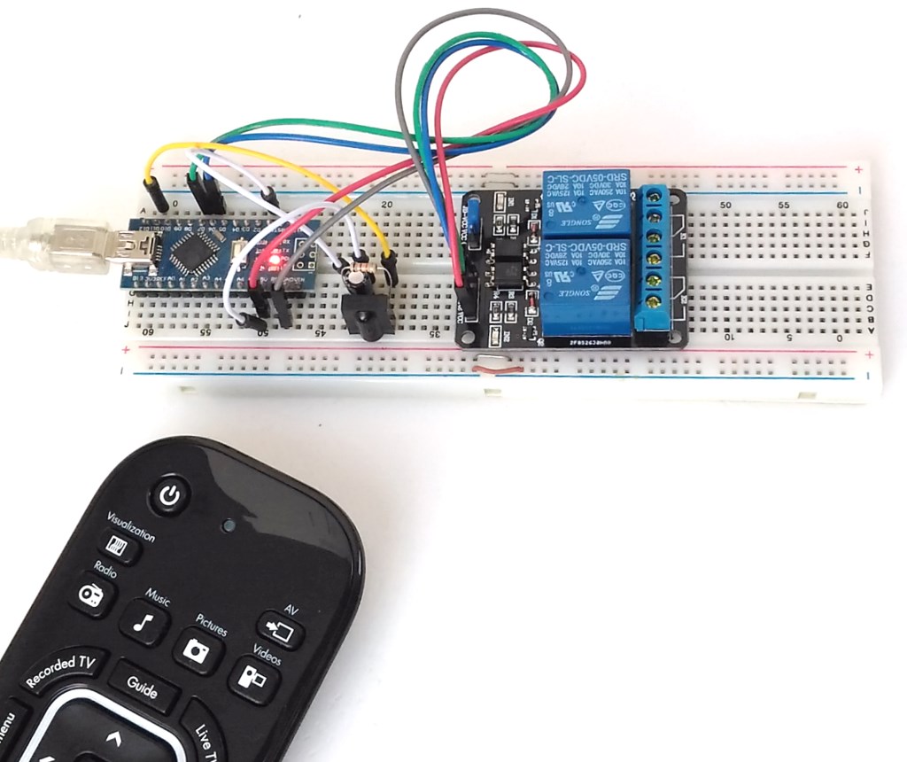
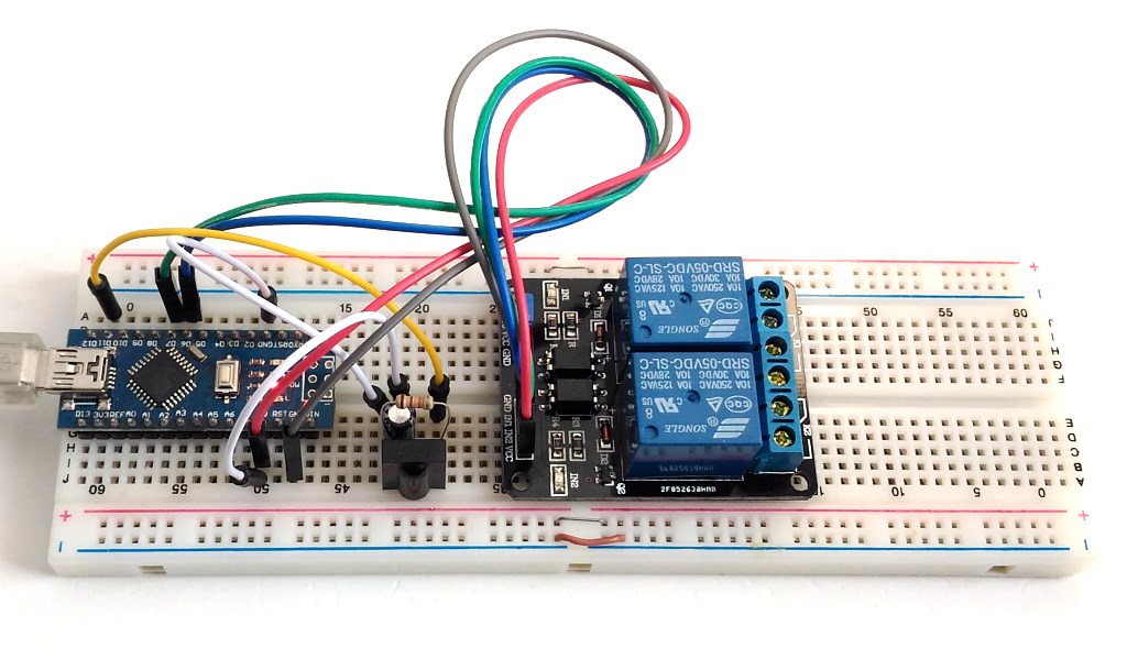
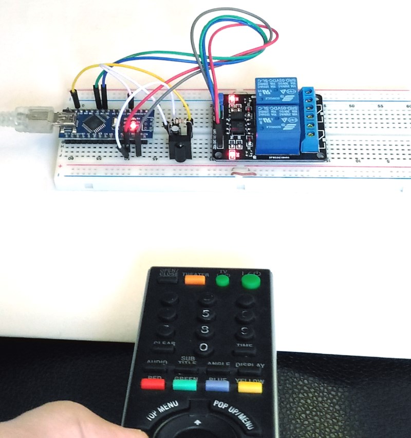
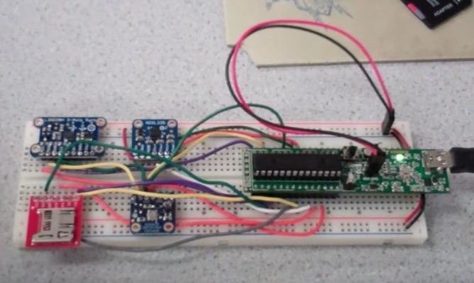
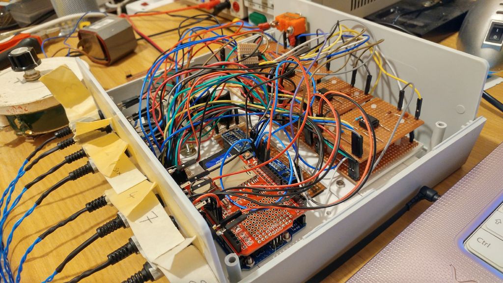
Shown below is the complete hardware setup made on a breadboard. An Arduino Nano board is used in this project.
![Complete circuit setup on a breadboard]()
Complete circuit setup on a breadboard
Software
After the hardware setup is complete, we will now program the Arduino Nano to receive the TSOP1738 demodulated output and interpret the codes for individual button presses on the remote. There are many different infrared protocol standards or data formats that are designed by different manufacturers for use in consumer electronics. The most commonly used protocols are RC-5 and RC-6 from Philips, SIRC from Sony, NEC, JVC, Sharp, and Nokia NRC17. Each of these protocols have their own formats of sending data, which consists of some address bits and some command bits. Describing each of these protocols is beyond the scope of this article. I would suggest the interested readers to look online if they want more details, or check out the following links.
Vishay Document (Data Formats for IR Remote Control)
AN1064 Microchip Application note
We have a really nice IRremote library, contributed by Ken Shirriff, that allows you to transmit and send infrared remote control codes in different data formats using Arduino. We are using this library to decode the IR codes transmitted by an IR remote. In this example, I am using a Sony brand Blueray Disc player remote, which uses SIRC protocol for sending IR data.
We will develop the Arduino firmware for this project in two steps. First, we will write a simple program to find out the numeric codes (or decimal values) for specific buttons on the remote. It will read the IR receiver output, decode the message, and print out the type of protocol used and the decimal value for the transmitted code on a serial monitor window. The program to do that is posted below (code is adapted from IRrelay example written by Ken Shirriff).
#include <IRremote.h>

int RECV_PIN = 11;
IRrecv irrecv(RECV_PIN);
decode_results results;

void dump(decode_results *results) {
 int count = results->rawlen;
 if (results->decode_type == UNKNOWN) {
 Serial.println("Could not decode message");
 }
 else {
 Serial.println("Signal received.");
 if (results->decode_type == NEC) {
 Serial.print("Decoded NEC, ");
 }
 else if (results->decode_type == SONY) {
 Serial.print("Decoded SONY, ");
 }
 else if (results->decode_type == RC5) {
 Serial.print("Decoded RC5, ");
 }
 else if (results->decode_type == RC6) {
 Serial.print("Decoded RC6, ");
 }
 Serial.print("Value= ");
 Serial.print(results->value, DEC);
 Serial.print(" (");
 Serial.print(results->bits, DEC);
 Serial.println(" bits)");
 }

}

void setup()
{
 Serial.begin(9600);
 Serial.println("IR decoder");
 irrecv.enableIRIn(); // Start the receiver
}

int on = 0;
unsigned long last = millis();

void loop() {
 if (irrecv.decode(&results)) {
 // Wait for 0.5sec before decoding another code
 if (millis() - last > 500) {

 dump(&results);
 }
 last = millis();
 irrecv.resume(); // Receive the next value
 }
}
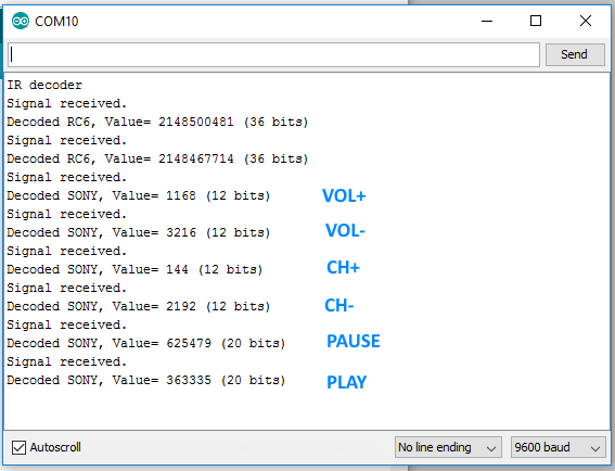
The hardware setup for this test program is not different than what was described above. Now, you aim a remote towards the TSOP1740 module on the breadboard and press a button, and you will see the decoded decimal value for that button displayed on the serial monitor window. Make sure the serial monitor baud rate is selected to be 9600. If your remote uses a different data coding scheme that is not present in the list of supported protocols of the IRremote library, then it won’t be able to decode the code. I tested it with two different remotes: one came with my Sony Blueray player and another with my HP All-in-one computer. It was able to decode both. I could see on the serial monitor window that the HP remote uses Philips RC-6 protocol, while Sony uses its own SIRC protocol. With my Sony remote, I noted down the decimal codes for VOL+, VOL-, CH+, CH-, PAUSE, and PLAY buttons on the remote, as displayed below.
![testserialmonitor]()
Decoding the IR message
Now we know what code is sent out for specific button presses, we can modify the code to implement additional logic for switching the relay circuits. We will program the Arduino to perform the following logic.
When VOL+ is pressed, Relay1 is turned ON.
When VOL- is pressed, Relay1 is turned OFF.
When CH+ is pressed, Relay2 is turned ON.
When CH- is pressed, Relay2 is turned OFF.
When PAUSE button is pressed, both relays are turned OFF.
When PLAY button is pressed, both relays are turned ON.
The following code does this task.
/* Project: Arduino relay switch using an IR remote control
 *
 * Raj Bhatt (Nov 25, 2016)
 * http://www.embedded-lab.com
*/


#include <IRremote.h>
#define SW1 6 // Relay control pins are 6 and 7
#define SW2 7

int RECV_PIN = 11; // IR receive pin is 11
IRrecv irrecv(RECV_PIN);
long int decodedCode;

decode_results rcv;

void controlRelays(){
 if(decodedCode == 1168) digitalWrite(SW1, LOW);
 if(decodedCode == 3216) digitalWrite(SW1, HIGH);
 if(decodedCode == 144) digitalWrite(SW2, LOW);
 if(decodedCode == 2192) digitalWrite(SW2, HIGH);
 if(decodedCode == 625479){
 digitalWrite(SW1, HIGH); // All off
 digitalWrite(SW2, HIGH);
 }

 if(decodedCode == 363335){
 digitalWrite(SW1, LOW); // All on
 digitalWrite(SW2, LOW);
 }
 delay(300);
}

void setup(){
 pinMode(SW1, OUTPUT);
 pinMode(SW2, OUTPUT);
 digitalWrite(SW1, HIGH); // Relay is active low, so HIGH will turn it off at startup
 digitalWrite(SW2, HIGH);
 Serial.begin(9600);
 Serial.println("IR relay controller");
 irrecv.enableIRIn();
}

void loop(){
 if (irrecv.decode(&rcv)) {
 Serial.print("Signal received, Value= ");
 decodedCode = rcv.value;
 Serial.println(decodedCode, DEC);
 controlRelays();
 irrecv.resume();
 }
}
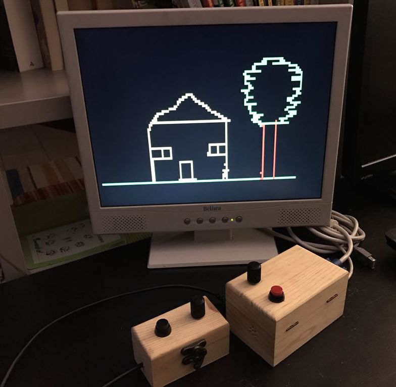
Output
After uploading the program to Arduino, enjoy the fun of turning the relays ON and OFF with the remote. You can easily add more relays to other free I/O pins of Arduino and add more if statements to control them in a similar fashion.
![IR]()
Controlling relays with a Sony Blueray Disc Player remote
The post Controlling relay switches with an infrared remote appeared first on Embedded Lab.
![]()