This post is a continuation of the previous post on Nuvoton N76E003 microcontroller here.
Communication Peripheral Overview
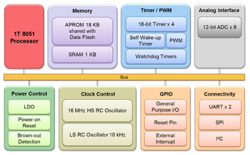
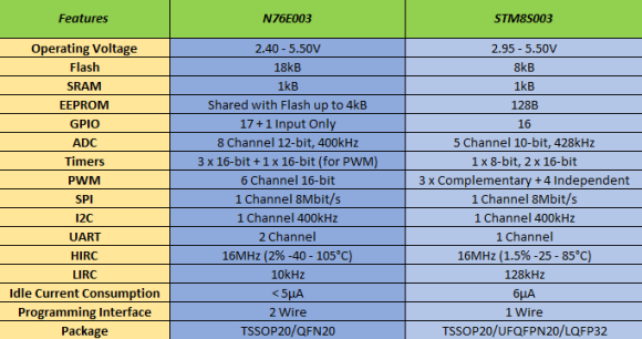
N76E003 packs basic serial communication peripherals for I2C, SPI and UART. These interfaces enable us to interface external EEPROM and flash memories, real-time clocks (RTC), sensors, etc.
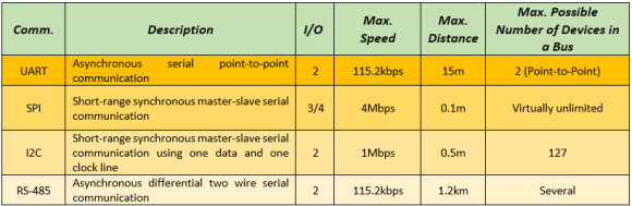
N76E003 has two hardware UARTs, one SPI and one I2C peripheral. The UART interfaces can be further expanded to implement RS-485 and RS-422 communication protocols. With ordinary GPIOs and optionally with hardware timers we can implement software-based UART, SPI and I2C too. However, software methods are slow and resource-hungry. Software-based approach is, on the other hand, needed when we have to interface devices that don’t use any of these communication topologies. For example, the one-wire protocol used by DHT series relative humidity and temperature sensors needs to be implemented by using an ordinary GPIO pin. Same goes for typical text and graphical LCDs.
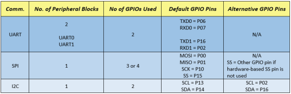
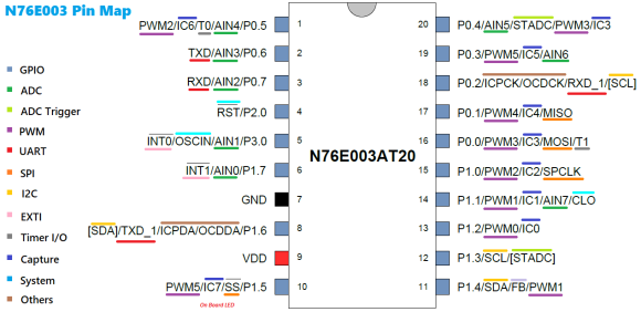
Note that there is a conflict between UART1 and alternative I2C pins. There are also similar conflicts with other hardware peripherals like PWMs, ADCs, etc since N76E003 packs lots of stuff in such a small form-factor. Every single GPIO pin is precious. Try to keep things with default GPIO pins in order to reduce conflicts with other hardware peripherals, coding and to maximize effective use of GPIOs. Likewise bear in mind that timers have also such conflicts as they are used to implement both hardware-based delays and the UART peripherals. You have to know for sure what you are doing, what do you want and with which stuffs you wish to accomplish your task.
Serial Communication – UART
To date serial communication (UART) is perhaps the simplest and widely used form of communication in use. UART block is only block available in most microcontrollers that can be easily interfaced with a computer or a phone. Most communication modules like Bluetooth, Wi-Fi, GSM modems, GPS modules, etc are interfaced using UART. It has incredible range and is also the backbone of other communication methods like RS-485, RS-422, etc.
To learn more about UART visit the following link:
https://learn.mikroe.com/uart-serial-communication
Code
HMC1022.h
#define Get_Angular_Measurement 0x31
#define Start_Calibration 0xC0
#define End_Calibration 0xC1
#define Set_Magnetic_Declination_High_Byte 0x03
#define Set_Magnetic_Declination_Low_Byte 0x04
#define no_of_data_bytes_returned 0x08
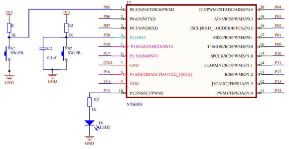
#define calibration_LED P15
void read_heading(void);
void calibrate_compass(void);
void factory_reset(void);
void set_declination_angle(unsigned long angle);
HMC1022.c
#include "N76E003.h"
#include "SFR_Macro.h"
#include "Function_define.h"
#include "Common.h"
#include "Delay.h"
#include "soft_delay.h"
#include "HMC1022.h"
unsigned char done = 0;
unsigned char data_bytes[no_of_data_bytes_returned] = {0x00, 0x00, 0x00, 0x00, 0x00, 0x00};
void read_heading(void)
{
unsigned char s = 0;
unsigned long CRC = 0;
Send_Data_To_UART1(Get_Angular_Measurement);
for(s = 0; s < no_of_data_bytes_returned; s++)
{
data_bytes[s] = Receive_Data_From_UART1();
if(s < (no_of_data_bytes_returned - 1))
{
CRC += data_bytes[s];
}
}
CRC = (CRC & 0xFF);
if(CRC == data_bytes[7])
{
done = 1;
}
}
void calibrate_compass(void)
{
unsigned char s = 0x00;
Send_Data_To_UART1(Start_Calibration);
for(s = 0; s < 60; s++)
{
calibration_LED = 1;
delay_ms(100);
calibration_LED = 0;
delay_ms(900);
}
for(s = 0; s < 60; s++)
{
calibration_LED = 1;
delay_ms(400);
calibration_LED = 0;
delay_ms(600);
}
Send_Data_To_UART1(End_Calibration);
}
void factory_reset(void)
{
Send_Data_To_UART1(0xA0);
Send_Data_To_UART1(0xAA);
Send_Data_To_UART1(0xA5);
Send_Data_To_UART1(0xC5);
}
void set_declination_angle(unsigned long angle)
{
unsigned long hb = 0;
unsigned char lb = 0;
lb = (angle & 0x00FF);
hb = (angle & 0xFF00);
hb >>= 8;
Send_Data_To_UART1(Set_Magnetic_Declination_High_Byte);
Send_Data_To_UART1(hb);
Send_Data_To_UART1(Set_Magnetic_Declination_Low_Byte);
Send_Data_To_UART1(lb);
}
main.c
#include "N76E003.h"
#include "SFR_Macro.h"
#include "Function_define.h"
#include "Common.h"
#include "Delay.h"
#include "soft_delay.h"
#include "LCD_2_Wire.h"
#include "HMC1022.h"
const unsigned char symbol[8] =
{
0x00, 0x06, 0x09, 0x09, 0x06, 0x00, 0x00, 0x00
};
extern unsigned char done;
extern unsigned char data_bytes[no_of_data_bytes_returned];
void setup(void);
void lcd_symbol(void);
void main(void)
{
setup();
while(1)
{
read_heading();
if(done)
{
LCD_goto(6, 1);
LCD_putchar(data_bytes[2]);
LCD_goto(7, 1);
LCD_putchar(data_bytes[3]);
LCD_goto(8, 1);
LCD_putchar(data_bytes[4]);
LCD_goto(9, 1);
LCD_putchar('.');
LCD_goto(10, 1);
LCD_putchar(data_bytes[6]);
done = 0;
}
P15 = ~P15;
delay_ms(200);
};
}
void setup(void)
{
P15_PushPull_Mode;
LCD_init();
LCD_clear_home();
lcd_symbol();
LCD_goto(3, 0);
LCD_putstr("Heading N");
LCD_goto(11, 0);
LCD_send(0, DAT);
InitialUART1_Timer3(9600);
}
void lcd_symbol(void)
{
unsigned char s = 0;
LCD_send(0x40, CMD);
for(s = 0; s < 8; s++)
{
LCD_send(symbol[s], DAT);
}
LCD_send(0x80, CMD);
}
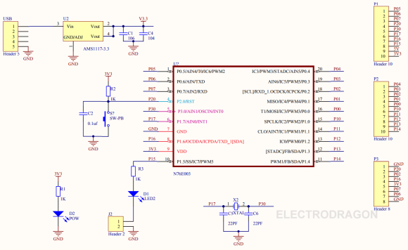
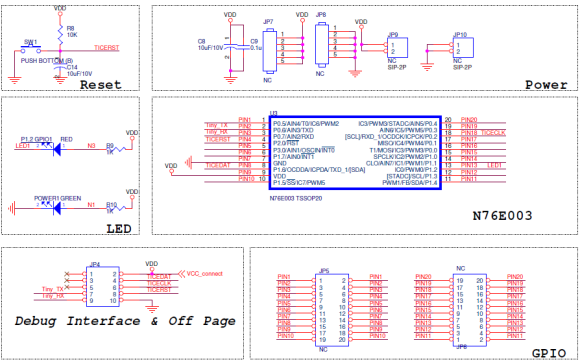
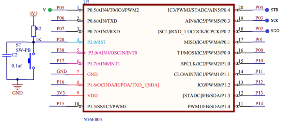
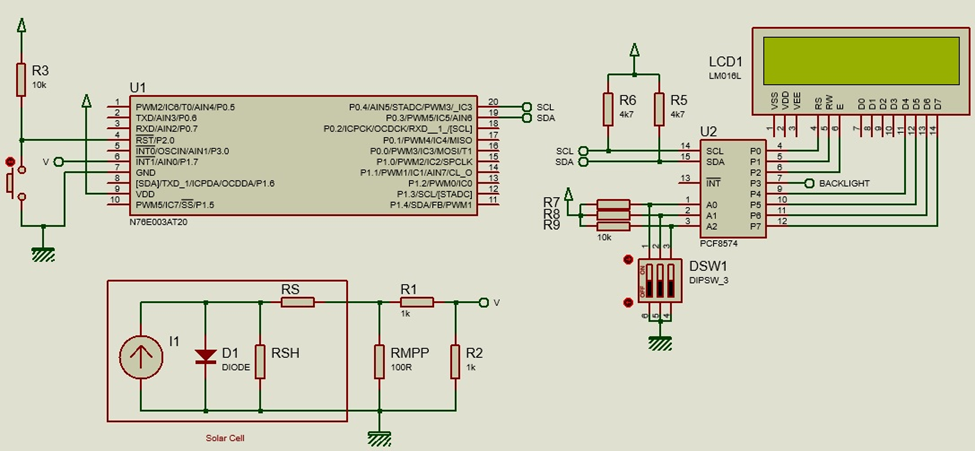
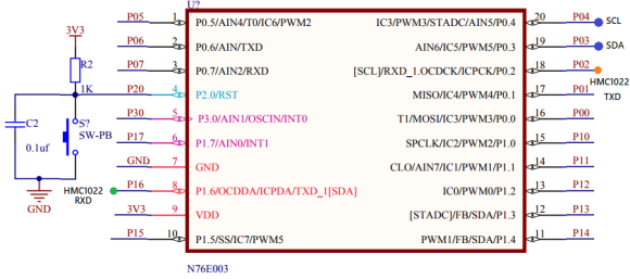
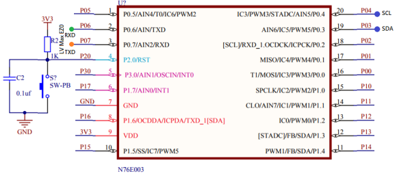
Schematic
Explanation
The following are the commands that HMC1022 acknowledges when sent via UART:
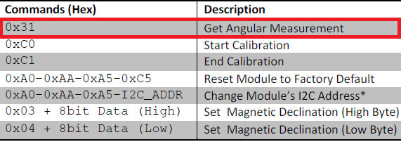
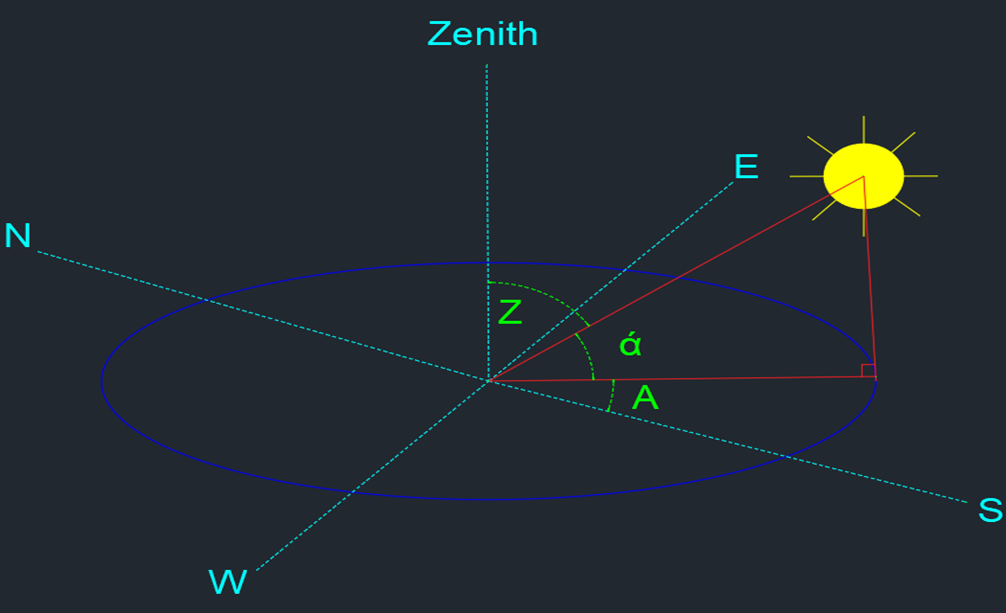
HMC1022 gives heading data when it is requested. The highlighted command is that command.
Once requested it sends out a string of characters that carry heading information. The followings are the response package and its details:
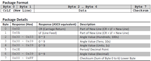
From the above info, it is clear that HMC1022 will return 8 bytes when requested for heading. Out of these we need bytes 2, 3,4 and 6. The rest can be ignored for simplicity.
Data from HM1022 is received by the following function:
void read_heading(void)
{
unsigned char s = 0;
unsigned long CRC = 0;
Send_Data_To_UART1(Get_Angular_Measurement);
for(s = 0; s < no_of_data_bytes_returned; s++)
{
data_bytes[s] = Receive_Data_From_UART1();
if(s < (no_of_data_bytes_returned - 1))
{
CRC += data_bytes[s];
}
}
CRC = (CRC & 0xFF);
if(CRC == data_bytes[7])
{
done = 1;
}
}
Note that the function Send_Data_To_UART1 and Receive_Data_From_UART1 are BSP functions. Likewise, InitialUART1_Timer3(9600) function is also a BSP function that initiates UART1 with Timer 3. As with ADC, BSP functions for UART are enough for basic setup. Try to use Timer 3 as it remains mostly free. If you need more control over the UART, you can manually configure the registers.
In the main, the received bytes containing heading info are displayed.
Demo
UART Interrupt
UART, as we saw in the last example, can be used in polling mode but it is wise to use it in interrupt mode. This feature becomes especially important and therefore, a must-have requirement when it come to that fact that the host micro may not always know when to receive data. Unlike SPI/I2C, UART doesn’t always follow known data transactions. Take the example of a GSM modem. We and so does our tiny host N76E003 micro don’t know for sure when a message would arrive. Thus, when an interrupt due to reception is triggered, it is known to mark the beginning of data reception process. The host micro can relax idle until data is received fully.
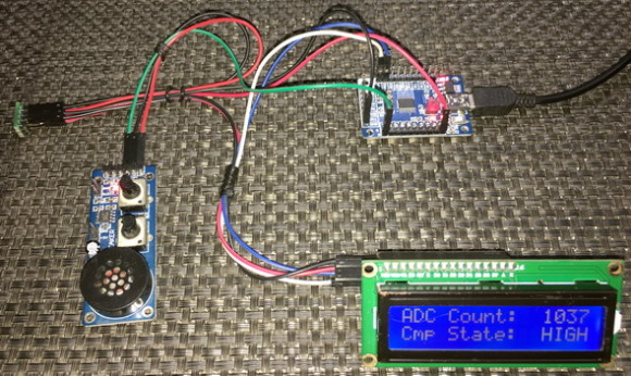
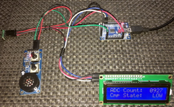
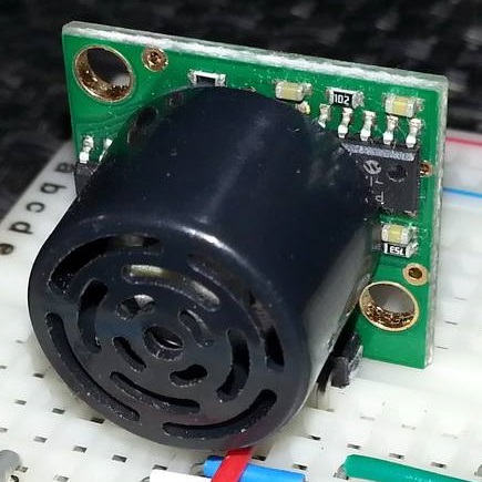
Here, we will see how to use UART interrupt to read a LV-Max EZ0 SONAR module.
Code
#include "N76E003.h"
#include "SFR_Macro.h"
#include "Function_define.h"
#include "Common.h"
#include "soft_delay.h"
#include "LCD_2_Wire.h"
unsigned char received = 0;
unsigned char count = 0;
unsigned char buffer[5] = {0x00, 0x00, 0x00, 0x00, 0x00};
void setup(void);
void UART0_ISR(void)
interrupt 4
{
if(RI == 1)
{
buffer[count] = SBUF;
count++;
if(count >= 4)
{
clr_ES;
received = 1;
}
clr_RI;
}
P15 = ~P15;
}
void main(void)
{
unsigned char i = 0;
setup();
while(1)
{
Send_Data_To_UART0('S');
delay_ms(40);
set_ES;
if(received)
{
for(i = 1; i < 4; i++)
{
LCD_goto((12 + i), 1);
LCD_putchar(buffer[i]);
}
count = 0;
received = 0;
set_ES;
}
delay_ms(40);
}
}
void setup(void)
{
P15_PushPull_Mode;
LCD_init();
LCD_clear_home();
LCD_goto(1, 0);
LCD_putstr("UART Interrupt");
LCD_goto(0, 1);
LCD_putstr("Range/Inch:");
InitialUART0_Timer3(9600);
set_EA;
}
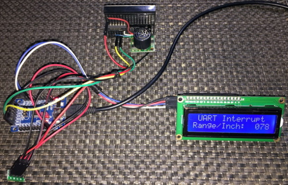
Schematic
*Note the LV-Max EZ0 SONAR sensor is not directly connected with the N76E003 as shown in the schematic but rather it is connected via a 74HC04 hex inverter. Two of these inverters are used – one for the TX side and the other for the RX side.
Explanation
This time UART0 is used and is setup using BSP built-in function. The only exception is the interrupt part. The global interrupt is enabled but not the UART interrupt.
InitialUART0_Timer3(9600);
set_EA;
The UART interrupt is only enabled after commanding the SONAR sensor:
Send_Data_To_UART0('S');
delay_ms(40);
set_ES;
This is done to avoid unnecessary reads.
The sensor is read inside the interrupt routine. The sensor outputs data as Rxxx<CR>. So, there are 5 bytes to read. The “R” in the readout works as a preamble or sync byte. The “xxx” part contains range info in inches. Finally, <CR> is a carriage return character. Therefore, every time a character is received an interrupt is triggered and the character is saved in an array. When all 5 bytes have been received, the display is updated. On exiting the interrupt, the interrupt flag is cleared. P15 is also toggled to visually indicate that an UART interrupt has been triggered.
void UART0_ISR(void)
interrupt 4
{
if(RI == 1)
{
buffer[count] = SBUF;
count++;
if(count >= 4)
{
clr_ES;
received = 1;
}
clr_RI;
}
P15 = ~P15;
}
Demo
Inter-Integrated Circuit (I2C) – Interfacing DS1307 I2C RTC
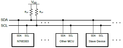
Developed by Philips nearly three decades ago, I2C communication (Inter-Integrated Circuit) is widely used in a number of devices and is comparatively easier than SPI. For I2C communication only two wires – serial data (SDA) and serial clock (SCK) are needed and these two wires form a bus in which we can connect up to 127 devices.
Everything you need to know about I2C can be found in these pages:
- https://learn.mikroe.com/i2c-everything-need-know
- https://learn.sparkfun.com/tutorials/i2c
- http://www.ti.com/lsds/ti/interface/i2c-overview.page
- http://www.robot-electronics.co.uk/i2c-tutorial
- https://www.i2c-bus.org/i2c-bus
- http://i2c.info
Apart from these N76E003’s datasheet explains I2C communication in high detail.
Code
I2C.h
#define regular_I2C_pins 0
#define alternate_I2C_pins 1
#define regular_I2C_GPIOs() do{P13_OpenDrain_Mode; P14_OpenDrain_Mode; clr_I2CPX;}while(0)
#define alternative_I2C_GPIOs() do{P02_OpenDrain_Mode; P16_OpenDrain_Mode; set_I2CPX;}while(0)
#define I2C_GPIO_Init(mode) do{if(mode != 0){alternative_I2C_GPIOs();}else{regular_I2C_GPIOs();}}while(0)
#define I2C_CLOCK 0x27 //Fclk = Fsys / (4*(prescalar + 1))
#define I2C_ACK 0
#define I2C_NACK 1
#define timeout_count 1000
void I2C_init(void);
void I2C_start(void);
void I2C_stop(void);
unsigned char I2C_read(unsigned char ack_mode);
void I2C_write(unsigned char value);
I2C.c
#include "N76E003.h"
#include "SFR_Macro.h"
#include "Function_define.h"
#include "Common.h"
#include "Delay.h"
#include "I2C.h"
void I2C_init(void)
{
I2C_GPIO_Init(regular_I2C_pins);
I2CLK = I2C_CLOCK;
set_I2CEN;
}
void I2C_start(void)
{
signed int t = timeout_count;
set_STA;
clr_SI;
while((SI == 0) && (t > 0))
{
t--;
};
}
void I2C_stop(void)
{
signed int t = timeout_count;
clr_SI;
set_STO;
while((STO == 1) && (t > 0))
{
t--;
};
}
unsigned char I2C_read(unsigned char ack_mode)
{
signed int t = timeout_count;
unsigned char value = 0x00;
set_AA;
clr_SI;
while((SI == 0) && (t > 0))
{
t--;
};
value = I2DAT;
if(ack_mode == I2C_NACK)
{
t = timeout_count;
clr_AA;
clr_SI;
while((SI == 0) && (t > 0))
{
t--;
};
}
return value;
}
void I2C_write(unsigned char value)
{
signed int t = timeout_count;
I2DAT = value;
clr_STA;
clr_SI;
while((SI == 0) && (t > 0))
{
t--;
};
}
DS1307.h
#define I2C_W 0
#define I2C_R 1
#define sec_reg 0x00
#define min_reg 0x01
#define hr_reg 0x02
#define day_reg 0x03
#define date_reg 0x04
#define month_reg 0x05
#define year_reg 0x06
#define control_reg 0x07
#define DS1307_addr 0xD0
#define DS1307_WR (DS1307_addr + I2C_W)
#define DS1307_RD (DS1307_addr + I2C_R)
void DS1307_init(void);
unsigned char DS1307_read(unsigned char address);
void DS1307_write(unsigned char address, unsigned char value);
unsigned char bcd_to_decimal(unsigned char value);
unsigned char decimal_to_bcd(unsigned char value);
void get_time(void);
void set_time(void);
DS1307.c
#include "N76E003.h"
#include "SFR_Macro.h"
#include "Function_define.h"
#include "Common.h"
#include "Delay.h"
#include "DS1307.h"
#include "I2C.h"
struct
{
unsigned char s;
unsigned char m;
unsigned char h;
unsigned char dy;
unsigned char dt;
unsigned char mt;
unsigned char yr;
}time;
void DS1307_init(void)
{
I2C_init();
DS1307_write(control_reg, 0x00);
}
unsigned char DS1307_read(unsigned char address)
{
unsigned char value = 0x00;
I2C_start();
I2C_write(DS1307_WR);
I2C_write(address);
I2C_start();
I2C_write(DS1307_RD);
value = I2C_read(I2C_NACK);
I2C_stop();
return value;
}
void DS1307_write(unsigned char address, unsigned char value)
{
I2C_start();
I2C_write(DS1307_WR);
I2C_write(address);
I2C_write(value);
I2C_stop();
}
unsigned char bcd_to_decimal(unsigned char value)
{
return ((value & 0x0F) + (((value & 0xF0) >> 0x04) * 0x0A));
}
unsigned char decimal_to_bcd(unsigned char value)
{
return (((value / 0x0A) << 0x04) & 0xF0) | ((value % 0x0A) & 0x0F);
}
void get_time(void)
{
time.s = DS1307_read(sec_reg);
time.s = bcd_to_decimal(time.s);
time.m = DS1307_read(min_reg);
time.m = bcd_to_decimal(time.m);
time.h = DS1307_read(hr_reg);
time.h = bcd_to_decimal(time.h);
time.dy = DS1307_read(day_reg);
time.dy = bcd_to_decimal(time.dy);
time.dt = DS1307_read(date_reg);
time.dt = bcd_to_decimal(time.dt);
time.mt = DS1307_read(month_reg);
time.mt = bcd_to_decimal(time.mt);
time.yr = DS1307_read(year_reg);
time.yr = bcd_to_decimal(time.yr);
}
void set_time(void)
{
time.s = decimal_to_bcd(time.s);
DS1307_write(sec_reg, time.s);
time.m = decimal_to_bcd(time.m);
DS1307_write(min_reg, time.m);
time.h = decimal_to_bcd(time.h);
DS1307_write(hr_reg, time.h);
time.dy = decimal_to_bcd(time.dy);
DS1307_write(day_reg, time.dy);
time.dt = decimal_to_bcd(time.dt);
DS1307_write(date_reg, time.dt);
time.mt = decimal_to_bcd(time.mt);
DS1307_write(month_reg, time.mt);
time.yr = decimal_to_bcd(time.yr);
DS1307_write(year_reg, time.yr);
}
main.c
#include "N76E003.h"
#include "SFR_Macro.h"
#include "Function_define.h"
#include "Common.h"
#include "Delay.h"
#include "soft_delay.h"
#include "LCD_3_Wire.h"
#include "I2C.h"
#include "DS1307.h"
extern struct
{
unsigned char s;
unsigned char m;
unsigned char h;
unsigned char dy;
unsigned char dt;
unsigned char mt;
unsigned char yr;
}time;
void show_value(unsigned char x_pos, unsigned char y_pos, unsigned char value);
void display_time(void);
void main(void)
{
time.s = 30;
time.m = 58;
time.h = 23;
P15_PushPull_Mode;
LCD_init();
LCD_clear_home();
LCD_goto(0, 0);
LCD_putstr("N76E003 I2C RTCC");
DS1307_init();
set_time();
while(1)
{
get_time();
display_time();
};
}
void show_value(unsigned char x_pos, unsigned char y_pos, unsigned char value)
{
unsigned char chr = 0;
chr = ((value / 10) + 0x30);
LCD_goto(x_pos, y_pos);
LCD_putchar(chr);
chr = ((value % 10) + 0x30);
LCD_goto((x_pos + 1), y_pos);
LCD_putchar(chr);
}
void display_time(void)
{
P15 ^= 1;
LCD_goto(6, 1);
LCD_putchar(' ');
LCD_goto(9, 1);
LCD_putchar(' ');
delay_ms(400);
show_value(4, 1, time.h);
show_value(7, 1, time.m);
show_value(10, 1, time.s);
LCD_goto(6, 1);
LCD_putchar(':');
LCD_goto(9, 1);
LCD_putchar(':');
delay_ms(400);
}
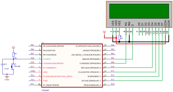
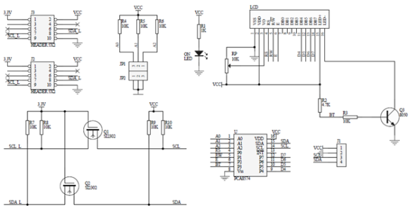
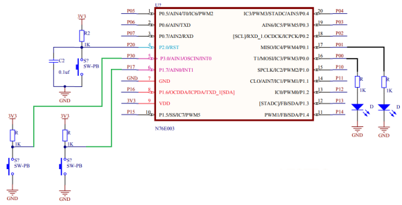
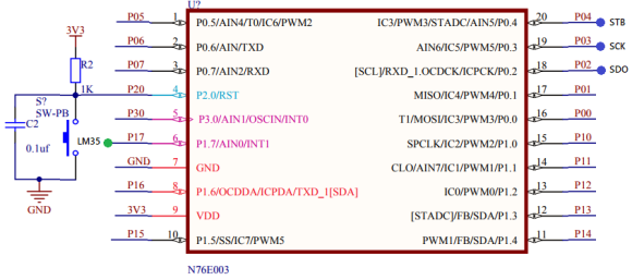
Schematic
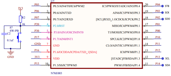
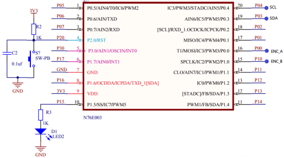
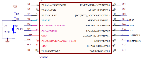
*Note that the pin naming of the chip in the schematic above is wrong. P13 and P14 are both SDA pins according to this naming when actually P13 is SCL and P14 is SDA pin.
Explanation
I have coded two files for I2C easy and quick I2C implementation. These are I2C header and source file. These files describe I2C hardware functionality as well as provide higher level functions under the hood of which I2C hardware is manipulated. I have only coded these files for master mode only since barely we would ever need N76E003 slaves. I also didn’t implement interrupt-based I2C functionalities as this, in my experience, is also not needed in most of the cases.
void I2C_init(void);
void I2C_start(void);
void I2C_stop(void);
unsigned char I2C_read(unsigned char ack_mode);
void I2C_write(unsigned char value);
Using hardware I2C requires us to manipulate the following registers apart from clock and GPIO settings.
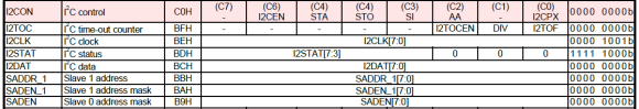
I2C GPIOs must be set as open-drain GPIOs as per I2C standard. I2C clock must be set according to the devices connected in the bus. Typically, I2C clock speed ranges from 20 – 400kHz. This clock speed is dependent on system clock speed Fsys. Therefore, before setting I2C clock speed you have to set/know Fsys. I2C clock is decided by the value of I2CLK register. It is basically a prescalar value in master mode.
So, if Fsys = 16MHz and I2CLK = 39 (0x27), the I2C bus clock rate is 100kHz.
Note that only in master I2C clock can be setup. In slave mode, the slave(s) synchronizes automatically with bus clock.
I2CON register is they key register for using I2C. It contains all the flags and condition-makers.
For instance, consider the I2C start condition. In order to make a start condition, we have to set the STA bit and clear I2C interrupt flag, SI. Since I used polling mode, SI is polled until it is cleared. This ensures that a start condition has been successfully made. I have also added a software-based timeout feature should there be an issue with the I2C bus. In N76E003, there is a hardware-based approach for timeout too. Note that I didn’t care about the I2C status register states as again this is rarely needed. If you want more grip on the I2C you can follow the BSP examples.
void I2C_start(void)
{
signed int t = timeout_count;
set_STA;
clr_SI;
while((SI == 0) && (t > 0))
{
t--;
};
}
Finally, the last register that we will need is the I2C data register (I2DAT). It is through it we send and receive data from I2C bus.
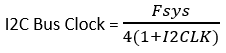
The demo I have shown here is that of a DS1307 I2C-based real time clock. Perhaps this is the simplest device for learning about and understanding I2C.
Demo
Serial Peripheral Interface (SPI) – Interfacing MAX7219 and MAX6675
SPI just like I2C is another highly popular form of onboard serial communication. Compared to I2C it is fast and robust. However, it requires more GPIO pins than other communication forms. These make it ideal communication interface for TFT displays, OLED displays, flash memories, DACs, etc.
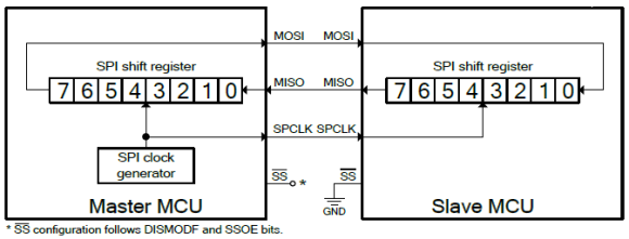
SPI is best realized as a shift register that shifts data in and out with clock pulses. In a SPI bus, there is always one master device which generates clock and selects slave(s). Master sends commands to slave(s). Slave(s) responds to commands sent by the master. The number of slaves in a SPI bus is virtually unlimited. Except the chip selection pin, all SPI devices in a bus can share the same clock and data pins.
In general, if you wish to know more about SPI bus here are some cool links:
- https://learn.mikroe.com/spi-bus
- https://learn.sparkfun.com/tutorials/serial-peripheral-interface-spi
- http://ww1.microchip.com/downloads/en/devicedoc/spi.pdf
- http://tronixstuff.com/2011/05/13/tutorial-arduino-and-the-spi-bus
- https://embeddedmicro.com/tutorials/mojo/serial-peripheral-interface-spi
- http://www.circuitbasics.com/basics-of-the-spi-communication-protocol
Code
MAX72xx.h
#define MAX72xx_SPI_GPIO_init() do{P00_PushPull_Mode; P10_PushPull_Mode; P11_PushPull_Mode;}while(0)
#define MAX72xx_CS_OUT_HIGH() set_P11
#define MAX72xx_CS_OUT_LOW() clr_P11
#define NOP 0x00
#define DIG0 0x01
#define DIG1 0x02
#define DIG2 0x03
#define DIG3 0x04
#define DIG4 0x05
#define DIG5 0x06
#define DIG6 0x07
#define DIG7 0x08
#define decode_mode_reg 0x09
#define intensity_reg 0x0A
#define scan_limit_reg 0x0B
#define shutdown_reg 0x0C
#define display_test_reg 0x0F
#define shutdown_cmd 0x00
#define run_cmd 0x01
#define no_test_cmd 0x00
#define test_cmd 0x01
#define digit_0_only 0x00
#define digit_0_to_1 0x01
#define digit_0_to_2 0x02
#define digit_0_to_3 0x03
#define digit_0_to_4 0x04
#define digit_0_to_5 0x05
#define digit_0_to_6 0x06
#define digit_0_to_7 0x07
#define No_decode_for_all 0x00
#define Code_B_decode_digit_0 0x01
#define Code_B_decode_digit_0_to_3 0x0F
#define Code_B_decode_for_all 0xFF
void MAX72xx_SPI_HW_Init(unsigned char clk_value);
void MAX72xx_init(void);
void MAX72xx_write(unsigned char address, unsigned char value);
MAX72xx.c
#include "N76E003_IAR.h"
#include "SFR_Macro.h"
#include "Function_define.h"
#include "Common.h"
#include "Delay.h"
#include "MAX72xx.h"
void MAX72xx_SPI_HW_Init(unsigned char clk_value)
{
switch(clk_value)
{
case 1:
{
clr_SPR1;
set_SPR0;
break;
}
case 2:
{
set_SPR1;
clr_SPR0;
break;
}
case 3:
{
set_SPR1;
set_SPR0;
break;
}
default:
{
clr_SPR1;
clr_SPR0;
break;
}
}
set_DISMODF;
set_MSTR;
clr_CPOL;
clr_CPHA;
set_SPIEN;
}
void MAX72xx_init(void)
{
MAX72xx_SPI_GPIO_init();
MAX72xx_SPI_HW_Init(0);
MAX72xx_write(shutdown_reg, run_cmd);
MAX72xx_write(decode_mode_reg, Code_B_decode_digit_0_to_3);
MAX72xx_write(scan_limit_reg, digit_0_to_3);
MAX72xx_write(intensity_reg, 0x19);
}
void MAX72xx_write(unsigned char address, unsigned char value)
{
MAX72xx_CS_OUT_LOW();
SPDR = address;
while(!(SPSR & SET_BIT7));
clr_SPIF;
SPDR = value;
while(!(SPSR & SET_BIT7));
clr_SPIF;
MAX72xx_CS_OUT_HIGH();
}
MAX6675.h
#define MAX6675_SPI_GPIO_init() do{P01_Input_Mode; P10_PushPull_Mode; P12_PushPull_Mode;}while(0)
#define MAX6675_CS_OUT_HIGH() set_P12
#define MAX6675_CS_OUT_LOW() clr_P12
#define T_min 0
#define T_max 1024
#define count_max 4096
#define no_of_pulses 16
#define deg_C 0
#define deg_F 1
#define tmp_K 2
#define open_contact 0x04
#define close_contact 0x00
#define scalar_deg_C 0.25
#define scalar_deg_F_1 1.8
#define scalar_deg_F_2 32.0
#define scalar_tmp_K 273.0
#define no_of_samples 16
void MAX6675_SPI_HW_Init(unsigned char clk_value);
void MAX6675_init(void);
unsigned char MAX6675_get_ADC(unsigned int *ADC_data);
float MAX6675_get_T(unsigned int ADC_value, unsigned char T_unit);
MAX6675.c
#include "N76E003_IAR.h"
#include "SFR_Macro.h"
#include "Function_define.h"
#include "Common.h"
#include "Delay.h"
#include "MAX6675.h"
void MAX6675_SPI_HW_Init(unsigned char clk_value)
{
switch(clk_value)
{
case 1:
{
clr_SPR1;
set_SPR0;
break;
}
case 2:
{
set_SPR1;
clr_SPR0;
break;
}
case 3:
{
set_SPR1;
set_SPR0;
break;
}
default:
{
clr_SPR1;
clr_SPR0;
break;
}
}
set_DISMODF;
set_MSTR;
clr_CPOL;
set_CPHA;
set_SPIEN;
}
void MAX6675_init(void)
{
MAX6675_SPI_GPIO_init();
MAX6675_SPI_HW_Init(0);
}
unsigned char MAX6675_get_ADC(unsigned int *ADC_data)
{
unsigned char lb = 0;
unsigned char hb = 0;
unsigned char samples = no_of_samples;
unsigned int temp_data = 0;
unsigned long avg_value = 0;
while(samples > 0)
{
MAX6675_CS_OUT_LOW();
SPDR = 0x00;
while(!(SPSR & SET_BIT7));
hb = SPDR;
clr_SPIF;
SPDR = 0x00;
while(!(SPSR & SET_BIT7));
lb = SPDR;
clr_SPIF;
MAX6675_CS_OUT_HIGH();
temp_data = hb;
temp_data <<= 8;
temp_data |= lb;
temp_data &= 0x7FFF;
avg_value += (unsigned long)temp_data;
samples--;
Timer0_Delay1ms(10);
};
temp_data = (avg_value >> 4);
if((temp_data & 0x04) == close_contact)
{
*ADC_data = (temp_data >> 3);
return close_contact;
}
else
{
*ADC_data = (count_max + 1);
return open_contact;
}
}
float MAX6675_get_T(unsigned int ADC_value, unsigned char T_unit)
{
float tmp = 0.0;
tmp = (((float)ADC_value) * scalar_deg_C);
switch(T_unit)
{
case deg_F:
{
tmp *= scalar_deg_F_1;
tmp += scalar_deg_F_2;
break;
}
case tmp_K:
{
tmp += scalar_tmp_K;
break;
}
default:
{
break;
}
}
return tmp;
}
main.c
#include "N76E003_IAR.h"
#include "Common.h"
#include "Delay.h"
#include "SFR_Macro.h"
#include "Function_define.h"
#include "soft_delay.h"
#include "MAX72xx.h"
#include "MAX6675.h"
void main(void)
{
unsigned int ti = 0;
unsigned int t = 0;
P15_PushPull_Mode;
MAX6675_init();
MAX72xx_init();
while(1)
{
P15 = 1;
clr_CPOL;
set_CPHA;
MAX6675_get_ADC(&ti);
t = ((unsigned int)MAX6675_get_T(ti, tmp_K));
delay_ms(100);
P15 = 0;
clr_CPOL;
clr_CPHA;
MAX72xx_write(DIG3, ((t / 1000) % 10));
MAX72xx_write(DIG2, ((t / 100) % 10));
MAX72xx_write(DIG1, ((t / 10) % 10));
MAX72xx_write(DIG0, (t % 10));
delay_ms(100);
};
}
Schematic
Explanation
With SPI we have to deal with two things – first, the initialization and second, the data transfer process. Configuring SPI needs a few things to be set up. These are:
- SPI communication bus speed or simply clock speed
- Clock polarity
- Clock phase
- Orientation of data, i.e. MSB first or LSB first
- Master/slave status
- Optionally hardware slave selection pin use
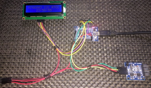
Most of these can be done by manipulating the following registers:
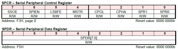
SPCR configures the hardware SPI peripheral of N76E003 while SPDR is used for transferring data.
To aid in all these I have coded the following functions. Though I didn’t use these code snippets in the actual demo code for demonstration purposes, these will most certainly work and reduce coding effort.
void SPI_init(unsigned char clk_speed, unsigned char mode)
{
set_SPI_clock_rate(clk_speed);
set_SPI_mode(mode);
set_DISMODF;
set_MSTR;
set_SPIEN;
}
unsigned char SPI_transfer(unsigned char write_value)
{
signed int t = timeout_count;
register unsigned char read_value = 0x00;
SPDR = write_value;
while((!(SPSR & SET_BIT7)) && (t > 0))
{
t--;
};
read_value = SPDR;
clr_SPIF;
return read_value;
}
SPI_init function sets up the SPI peripheral using two information – the bus clock speed and SPI data transfer mode. It initializes the SPI hardware as a SPI master device and without hardware salve selection pin. This configuration is mostly used in common interfacings. Only mode and clock speed are the variables. In the demo, it is visible that MAX7219 and MAX6675 work with different SPI modes. I also didn’t use the hardware slave selection because there are two devices and one slave pin. Certainly, both external devices are not driven at the same time although both share the same bus lines.
SPI_transfer reads and writes on the SPI bus. Here the master writes to the slave first, waits for successful transmission and reads from the slave later. It is best realized by the following figure:
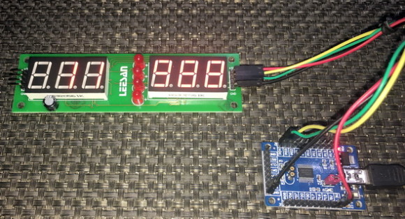
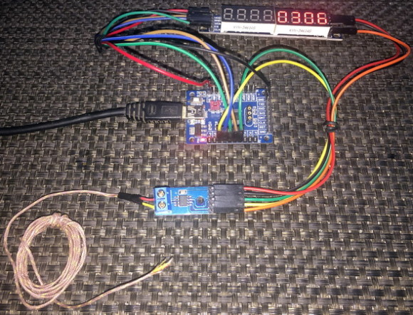
To demo SPI, MAX6675 and MAX7219 were used because one lacked read feature while the other lacked write feature. In the demo, MAX6675 is read to measure the temperature sensed by the K-type thermocouple attached with it and display the measured temperature in Kelvin on MAX7219-based seven segment display arrays.
Demo
One Wire (OW) Communication – Interfacing DHT11
One protocol is not a standard protocol like I2C or SPI. It is just a mere method of communicating with a device that uses just one wire. There are a few devices that uses such principle for communication. DHT series sensors, DS18B20s, digital serial number chips, etc. are a few to mention. As I stated before, since one wire communication doesn’t belong to a dedicated format of communication, there is no dedicated hardware for it. With just a bidirectional GPIO pin we can implement one wire communication. Optionally we can also use a timer for measuring response pulse widths since the method of sending ones and zeroes over one wire requires the measurement of pulse durations. This way of encoding ones and zeros as a function of pulse width is called time-slotting.
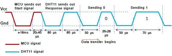
Shown above is the timing diagram for DHT11’s time slots. Check the length of pulse high time for one and zero. This is the technique applied in time-slotting mechanism. We have to time pulse lengths in order to identify the logic states.
Code
DHT11.h
#define HIGH 1
#define LOW 0
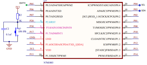
#define DHT11_pin_init() P05_Quasi_Mode
#define DHT11_pin_HIGH() set_P05
#define DHT11_pin_LOW() clr_P05
#define DHT11_pin_IN() P05
void DHT11_init(void);
unsigned char get_byte(void);
unsigned char get_data(void);
DHT11.c
#include "N76E003.h"
#include "SFR_Macro.h"
#include "Function_define.h"
#include "Common.h"
#include "Delay.h"
#include "soft_delay.h"
#include "DHT11.h"
extern unsigned char values[5];
void DHT11_init(void)
{
DHT11_pin_init();
delay_ms(1000);
}
unsigned char get_byte(void)
{
unsigned char s = 0;
unsigned char value = 0;
for(s = 0; s < 8; s++)
{
value <<= 1;
while(DHT11_pin_IN() == LOW);
delay_us(30);
if(DHT11_pin_IN() == HIGH)
{
value |= 1;
}
while(DHT11_pin_IN() == HIGH);
}
return value;
}
unsigned char get_data(void)
{
short chk = 0;
unsigned char s = 0;
unsigned char check_sum = 0;
DHT11_pin_HIGH();
DHT11_pin_LOW();
delay_ms(18);
DHT11_pin_HIGH();
delay_us(26);
chk = DHT11_pin_IN();
if(chk)
{
return 1;
}
delay_us(80);
chk = DHT11_pin_IN();
if(!chk)
{
return 2;
}
delay_us(80);
for(s = 0; s <= 4; s += 1)
{
values[s] = get_byte();
}
DHT11_pin_HIGH();
for(s = 0; s < 4; s += 1)
{
check_sum += values[s];
}
if(check_sum != values[4])
{
return 3;
}
else
{
return 0;
}
}
main.c
#include "N76E003.h"
#include "SFR_Macro.h"
#include "Function_define.h"
#include "Common.h"
#include "Delay.h"
#include "soft_delay.h"
#include "LCD_2_Wire.h"
#include "DHT11.h"
unsigned char values[5];
const unsigned char symbol[8] =
{
0x00, 0x06, 0x09, 0x09, 0x06, 0x00, 0x00, 0x00
};
void setup(void);
void lcd_symbol(void);
void lcd_print(unsigned char x_pos, unsigned char y_pos, unsigned char value);
void main(void)
{
unsigned char state = 0;
setup();
while(1)
{
state = get_data();
switch(state)
{
case 1:
{
}
case 2:
{
LCD_clear_home();
LCD_putstr("No Sensor Found!");
break;
}
case 3:
{
LCD_clear_home();
LCD_putstr("Checksum Error!");
break;
}
default:
{
LCD_goto(0, 0);
LCD_putstr("R.H/ %: ");
lcd_print(14, 0, values[0]);
LCD_goto(0, 1);
LCD_putstr("Tmp/");
LCD_goto(4, 1);
LCD_send(0, DAT);
LCD_goto(5, 1);
LCD_putstr("C:");
if((values[2] & 0x80) == 1)
{
LCD_goto(13, 1);
LCD_putstr("-");
}
else
{
LCD_goto(13, 1);
LCD_putstr(" ");
}
lcd_print(14, 1, values[2]);
break;
}
}
delay_ms(1000);
};
}
void setup(void)
{
DHT11_init();
LCD_init();
LCD_clear_home();
lcd_symbol();
}
void lcd_symbol(void)
{
unsigned char s = 0;
LCD_send(0x40, CMD);
for(s = 0; s < 8; s++)
{
LCD_send(symbol[s], DAT);
}
LCD_send(0x80, CMD);
}
void lcd_print(unsigned char x_pos, unsigned char y_pos, unsigned char value)
{
unsigned char chr = 0x00;
chr = ((value / 10) + 0x30);
LCD_goto(x_pos, y_pos);
LCD_putchar(chr);
chr = ((value % 10) + 0x30);
LCD_goto((x_pos + 1), y_pos);
LCD_putchar(chr);
}
Schematic
Explanation
As stated earlier, OW basically needs two things – first, the control of a single GPIO pin and second, the measurement of time. I would like to highlight the most important part of the whole code here:
unsigned char get_byte(void)
{
unsigned char s = 0;
unsigned char value = 0;
for(s = 0; s < 8; s++)
{
value <<= 1;
while(DHT11_pin_IN() == LOW);
delay_us(30);
if(DHT11_pin_IN() == HIGH)
{
value |= 1;
}
while(DHT11_pin_IN() == HIGH);
}
return value;
}
From DHT11’s timing diagram, we know that a zero is define by a pulse of 26 – 28μs and a logic one is defined by a pulse of 70μs. It is here in the get_byte function we check the pulse coming from DHT11. The DHT11’s pin is polled as an input and after 30μs if the result of this polling is high then it is considered as a logic one or else it is considered otherwise. Once triggered, DHT11 will provide a 5-byte output. All of the bits in these 5 bytes are checked this way. Though it is not the best method to do so, it is easy and simple.
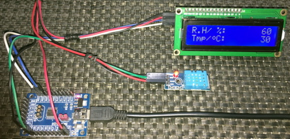
Demo
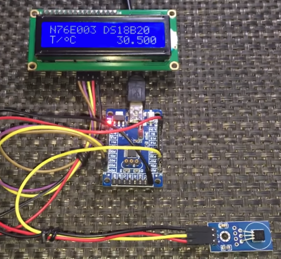
One Wire (OW) Communication – Interfacing DS18B20
One wire communication, as stated previously, doesn’t have a defined protocol. Except for the time-slotting mechanism part, there is nothing in common across the devices using this form of communication. We have seen how to interface a DHT11 relative humidity and temperature sensor previously. In this segment, we will see how to interface a DS18B20 one-wire digital temperature sensor with N76E003. DS18B20 follows and uses a completely different set of rules for communication.
Code
one_wire.h
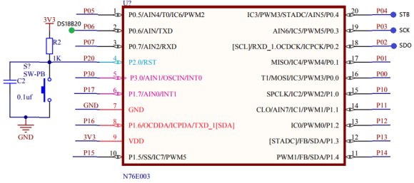
#define DS18B20_GPIO_init() P06_OpenDrain_Mode
#define DS18B20_IN() P06
#define DS18B20_OUT_LOW() clr_P06
#define DS18B20_OUT_HIGH() set_P06
#define TRUE 1
#define FALSE 0
unsigned char onewire_reset(void);
void onewire_write_bit(unsigned char bit_value);
unsigned char onewire_read_bit(void);
void onewire_write(unsigned char value);
unsigned char onewire_read(void);
one_wire.c
#include "N76E003.h"
#include "SFR_Macro.h"
#include "Function_define.h"
#include "Common.h"
#include "Delay.h"
#include "soft_delay.h"
#include "one_wire.h"
unsigned char onewire_reset(void)
{
unsigned char res = FALSE;
DS18B20_GPIO_init();
DS18B20_OUT_LOW();
delay_us(480);
DS18B20_OUT_HIGH();
delay_us(60);
res = DS18B20_IN();
delay_us(480);
return res;
}
void onewire_write_bit(unsigned char bit_value)
{
DS18B20_OUT_LOW();
if(bit_value)
{
delay_us(104);
DS18B20_OUT_HIGH();
}
}
unsigned char onewire_read_bit(void)
{
DS18B20_OUT_LOW();
DS18B20_OUT_HIGH();
delay_us(15);
return(DS18B20_IN());
}
void onewire_write(unsigned char value)
{
unsigned char s = 0;
while(s < 8)
{
if((value & (1 << s)))
{
DS18B20_OUT_LOW();
nop;
DS18B20_OUT_HIGH();
delay_us(60);
}
else
{
DS18B20_OUT_LOW();
delay_us(60);
DS18B20_OUT_HIGH();
nop;
}
s++;
}
}
unsigned char onewire_read(void)
{
unsigned char s = 0x00;
unsigned char value = 0x00;
while(s < 8)
{
DS18B20_OUT_LOW();
nop;
DS18B20_OUT_HIGH();
if(DS18B20_IN())
{
value |= (1 << s);
}
delay_us(60);
s++;
}
return value;
}
DS18B20.h
#include "one_wire.h"
#define convert_T 0x44
#define read_scratchpad 0xBE
#define write_scratchpad 0x4E
#define copy_scratchpad 0x48
#define recall_E2 0xB8
#define read_power_supply 0xB4
#define skip_ROM 0xCC
#define resolution 12
void DS18B20_init(void);
float DS18B20_get_temperature(void);
DS18B20.c
#include "N76E003.h"
#include "SFR_Macro.h"
#include "Function_define.h"
#include "Common.h"
#include "Delay.h"
#include "soft_delay.h"
#include "DS18B20.h"
void DS18B20_init(void)
{
onewire_reset();
delay_ms(100);
}
float DS18B20_get_temperature(void)
{
unsigned char msb = 0x00;
unsigned char lsb = 0x00;
register float temp = 0.0;
onewire_reset();
onewire_write(skip_ROM);
onewire_write(convert_T);
switch(resolution)
{
case 12:
{
delay_ms(750);
break;
}
case 11:
{
delay_ms(375);
break;
}
case 10:
{
delay_ms(188);
break;
}
case 9:
{
delay_ms(94);
break;
}
}
onewire_reset();
onewire_write(skip_ROM);
onewire_write(read_scratchpad);
lsb = onewire_read();
msb = onewire_read();
temp = msb;
temp *= 256.0;
temp += lsb;
switch(resolution)
{
case 12:
{
temp *= 0.0625;
break;
}
case 11:
{
temp *= 0.125;
break;
}
case 10:
{
temp *= 0.25;
break;
}
case 9:
{
temp *= 0.5;
break;
}
}
delay_ms(40);
return (temp);
}
main.c
#include "N76E003.h"
#include "SFR_Macro.h"
#include "Function_define.h"
#include "Common.h"
#include "Delay.h"
#include "soft_delay.h"
#include "DS18B20.h"
#include "LCD_3_Wire.h"
const unsigned char symbol[8] =
{
0x00, 0x06, 0x09, 0x09, 0x06, 0x00, 0x00, 0x00
};
void lcd_symbol(void);
void print_C(unsigned char x_pos, unsigned char y_pos, signed int value);
void print_I(unsigned char x_pos, unsigned char y_pos, signed long value);
void print_D(unsigned char x_pos, unsigned char y_pos, signed int value, unsigned char points);
void print_F(unsigned char x_pos, unsigned char y_pos, float value, unsigned char points);
void main(void)
{
float t = 0.0;
DS18B20_init();
LCD_init();
lcd_symbol();
LCD_goto(0, 0);
LCD_putstr("N76E003 DS18B20");
LCD_goto(0, 1);
LCD_putstr("T/ C");
LCD_goto(2, 1);
LCD_send(0, DAT);
while(1)
{
t = DS18B20_get_temperature();
print_F(9, 1, t, 3);
delay_ms(100);
};
}
void lcd_symbol(void)
{
unsigned char s = 0;
LCD_send(0x40, CMD);
for(s = 0; s < 8; s++)
{
LCD_send(symbol[s], DAT);
}
LCD_send(0x80, CMD);
}
void print_C(unsigned char x_pos, unsigned char y_pos, signed int value)
{
char ch[5] = {0x20, 0x20, 0x20, 0x20, '\0'};
if(value < 0x00)
{
ch[0] = 0x2D;
value = -value;
}
else
{
ch[0] = 0x20;
}
if((value > 99) && (value <= 999))
{
ch[1] = ((value / 100) + 0x30);
ch[2] = (((value % 100) / 10) + 0x30);
ch[3] = ((value % 10) + 0x30);
}
else if((value > 9) && (value <= 99))
{
ch[1] = (((value % 100) / 10) + 0x30);
ch[2] = ((value % 10) + 0x30);
ch[3] = 0x20;
}
else if((value >= 0) && (value <= 9))
{
ch[1] = ((value % 10) + 0x30);
ch[2] = 0x20;
ch[3] = 0x20;
}
LCD_goto(x_pos, y_pos);
LCD_putstr(ch);
}
void print_I(unsigned char x_pos, unsigned char y_pos, signed long value)
{
char ch[7] = {0x20, 0x20, 0x20, 0x20, 0x20, 0x20, '\0'};
if(value < 0)
{
ch[0] = 0x2D;
value = -value;
}
else
{
ch[0] = 0x20;
}
if(value > 9999)
{
ch[1] = ((value / 10000) + 0x30);
ch[2] = (((value % 10000)/ 1000) + 0x30);
ch[3] = (((value % 1000) / 100) + 0x30);
ch[4] = (((value % 100) / 10) + 0x30);
ch[5] = ((value % 10) + 0x30);
}
else if((value > 999) && (value <= 9999))
{
ch[1] = (((value % 10000)/ 1000) + 0x30);
ch[2] = (((value % 1000) / 100) + 0x30);
ch[3] = (((value % 100) / 10) + 0x30);
ch[4] = ((value % 10) + 0x30);
ch[5] = 0x20;
}
else if((value > 99) && (value <= 999))
{
ch[1] = (((value % 1000) / 100) + 0x30);
ch[2] = (((value % 100) / 10) + 0x30);
ch[3] = ((value % 10) + 0x30);
ch[4] = 0x20;
ch[5] = 0x20;
}
else if((value > 9) && (value <= 99))
{
ch[1] = (((value % 100) / 10) + 0x30);
ch[2] = ((value % 10) + 0x30);
ch[3] = 0x20;
ch[4] = 0x20;
ch[5] = 0x20;
}
else
{
ch[1] = ((value % 10) + 0x30);
ch[2] = 0x20;
ch[3] = 0x20;
ch[4] = 0x20;
ch[5] = 0x20;
}
LCD_goto(x_pos, y_pos);
LCD_putstr(ch);
}
void print_D(unsigned char x_pos, unsigned char y_pos, signed int value, unsigned char points)
{
char ch[5] = {0x2E, 0x20, 0x20, '\0'};
ch[1] = ((value / 100) + 0x30);
if(points > 1)
{
ch[2] = (((value / 10) % 10) + 0x30);
if(points > 1)
{
ch[3] = ((value % 10) + 0x30);
}
}
LCD_goto(x_pos, y_pos);
LCD_putstr(ch);
}
void print_F(unsigned char x_pos, unsigned char y_pos, float value, unsigned char points)
{
signed long tmp = 0x0000;
tmp = value;
print_I(x_pos, y_pos, tmp);
tmp = ((value - tmp) * 1000);
if(tmp < 0)
{
tmp = -tmp;
}
if(value < 0)
{
value = -value;
LCD_goto(x_pos, y_pos);
LCD_putchar(0x2D);
}
else
{
LCD_goto(x_pos, y_pos);
LCD_putchar(0x20);
}
if((value >= 10000) && (value < 100000))
{
print_D((x_pos + 6), y_pos, tmp, points);
}
else if((value >= 1000) && (value < 10000))
{
print_D((x_pos + 5), y_pos, tmp, points);
}
else if((value >= 100) && (value < 1000))
{
print_D((x_pos + 4), y_pos, tmp, points);
}
else if((value >= 10) && (value < 100))
{
print_D((x_pos + 3), y_pos, tmp, points);
}
else if(value < 10)
{
print_D((x_pos + 2), y_pos, tmp, points);
}
}
Schematic
Explanation
One wire communication is detailed in these application notes from Maxim:
https://www.maximintegrated.com/en/app-notes/index.mvp/id/126
https://www.maximintegrated.com/en/app-notes/index.mvp/id/162
These notes are all that are needed for implementing the one wire communication interface for DS18B20. Please go through these notes. The codes are self-explanatory and are implemented from the code examples in these app notes.
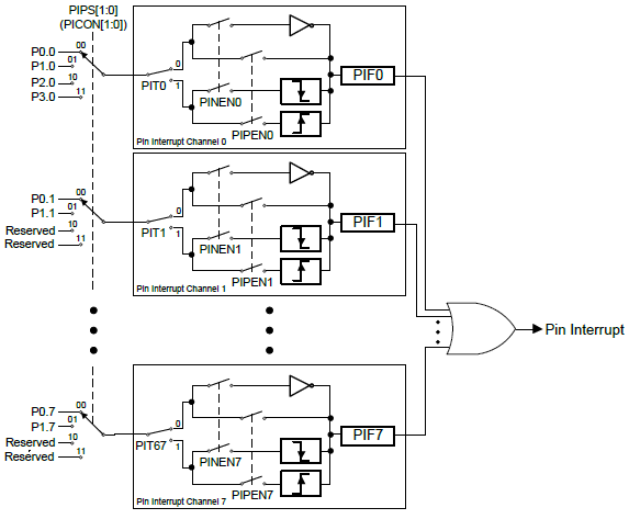
Decoding NEC IR Remote Protocol
IR remote controllers are used in a number of devices for remotely controlling them. Examples of these devices include TV, stereo, smart switches, projectors, etc. IR communication as such is unidirectional and in a way one wire communication. Ideally there is one transmitter and one receiver only.
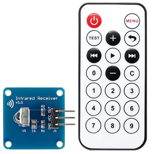
Data to be sent from a remote transmitter is sent by modulating it with a carrier wave (usually between 36kHz to 40kHz). Modulation ensure safety from data corruption and long-distance transmission. An IR receiver at the receiving end receives and demodulates the sent out modulated data and outputs a stream of pulses. These pulses which vary in pulse widths/timing/position/phase carry the data information that was originally sent by the remote transmitter. How the pulses should behave is governed closely by a protocol or defined set of rules. In most micros, there is no dedicated hardware for decoding IR remote protocols. A micro that needs to decode IR remote data also doesn’t know when it will be receiving an IR data stream. Thus, a combination of external interrupt and timer is needed for decoding IR data.
In this segment, we will see how we can use an external interrupt and a timer to easily decode a NEC IR remote. This same method can be applied to any IR remote controller. At this stage, I recommend that you do a study of NEC IR protocol from here. SB-Project’s website is an excellent page for info as such.
Code
#include "N76E003.h"
#include "SFR_Macro.h"
#include "Function_define.h"
#include "Common.h"
#include "Delay.h"
#include "soft_delay.h"
#include "LCD_2_Wire.h"
#define sync_high 22000
#define sync_low 14000
#define one_high 3600
#define one_low 2400
#define zero_high 1800
#define zero_low 1200
bit received;
unsigned char bits = 0;
unsigned int frames[33];
void setup(void);
void set_Timer_0(unsigned int value);
unsigned int get_Timer_0(void);
void erase_frames(void);
unsigned char decode(unsigned char start_pos, unsigned char end_pos);
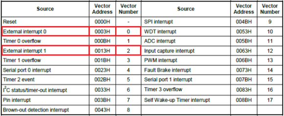
void decode_NEC(unsigned char *addr, unsigned char *cmd);
void lcd_print(unsigned char x_pos, unsigned char y_pos, unsigned char value);
void EXTI0_ISR(void)
interrupt 0
{
frames[bits] = get_Timer_0();
bits++;
set_TR0;
if(bits >= 33)
{
received = 1;
clr_EA;
clr_TR0;
}
set_Timer_0(0x0000);
P15 = ~P15;
}
void main(void)
{
unsigned char address = 0x00;
unsigned char command = 0x00;
setup();
while(1)
{
if(received)
{
decode_NEC(&address, &command);
lcd_print(13, 0, address);
lcd_print(13, 1, command);
delay_ms(100);
erase_frames();
set_EA;
}
};
}
void setup(void)
{
erase_frames();
P15_PushPull_Mode;
TIMER0_MODE1_ENABLE;
set_Timer_0(0x0000);
set_IT0;
set_EX0;
set_EA;
LCD_init();
LCD_clear_home();
LCD_goto(0, 0);
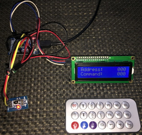
LCD_putstr("Address:");
LCD_goto(0, 1);
LCD_putstr("Command:");
}
void set_Timer_0(unsigned int value)
{
TH0 = ((value && 0xFF00) >> 8);
TL0 = (value & 0x00FF);
}
unsigned int get_Timer_0(void)
{
unsigned int value = 0x0000;
value = TH0;
value <<= 8;
value |= TL0;
return value;
}
void erase_frames(void)
{
for(bits = 0; bits < 33; bits++)
{
frames[bits] = 0x0000;
}
set_Timer_0(0x0000);
received = 0;
bits = 0;
}
unsigned char decode(unsigned char start_pos, unsigned char end_pos)
{
unsigned char value = 0;
for(bits = start_pos; bits <= end_pos; bits++)
{
value <<= 1;
if((frames[bits] >= one_low) && (frames[bits] <= one_high))
{
value |= 1;
}
else if((frames[bits] >= zero_low) && (frames[bits] <= zero_high))
{
value |= 0;
}
else if((frames[bits] >= sync_low) && (frames[bits] <= sync_high))
{
return 0xFF;
}
}
return value;
}
void decode_NEC(unsigned char *addr, unsigned char *cmd)
{
*addr = decode(2, 9);
*cmd = decode(18, 25);
}
void lcd_print(unsigned char x_pos, unsigned char y_pos, unsigned char value)
{
LCD_goto(x_pos, y_pos);
LCD_putchar((value / 100) + 0x30);
LCD_goto((x_pos + 1), y_pos);
LCD_putchar(((value % 10) / 10) + 0x30);
LCD_goto((x_pos + 2), y_pos);
LCD_putchar((value % 10) + 0x30);
}
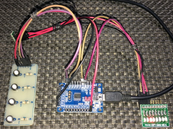
Schematic
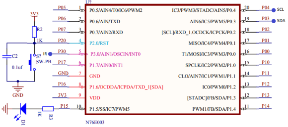
Explanation
A NEC transmission sends out 33 pulses. The first one is a sync bit and the rest 32 contain address and command info. These 32 address and command bits can be divided into 4 groups – address, command, inverted address and inverted command. The first 16 bits contain address and inverted address while the rest contain command and inverted command. The inverted signals can be used against the non-inverted ones for checking signal integrity.
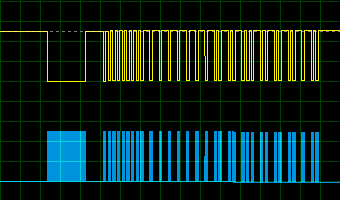
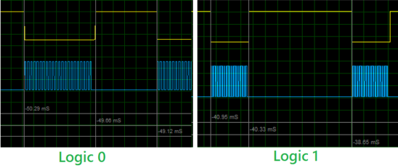
We already know that IR data is received as a steam of pulses. Pulses represent sync bit or other info, ones and zeros. In case of NEC IR protocol, the pulses have variable lengths. Sync bit represented by a pulse of 9ms high and 4.5ms low – total pulse time is 13.5ms. Check the timing diagram below. Please note that in this timing diagram the blue pulses are from the transmitter’s output and the yellow ones are those received by the receiver. Clearly the pulses are inverted.
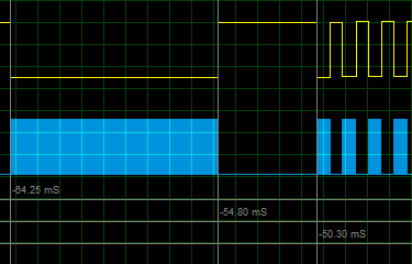
Logic one is represented by a pulse of 560µs high time and 2.25ms of low time – total pulse time is 2.81ms. Likewise, logic zero is represented by a pulse of 560µs high time and 1.12ms of low time – total pulse time is 1.68ms.
These timings can vary slightly about 15 – 25% due to a number of factors like medium, temperature, etc. Therefore, we can assume the following timings:
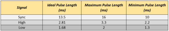
Now as per timing info and timing diagram we have to detect falling edges and time how long it takes to detect another falling edge. In this way, we can time the received pulses and use the pulse time info to decode a received signal.
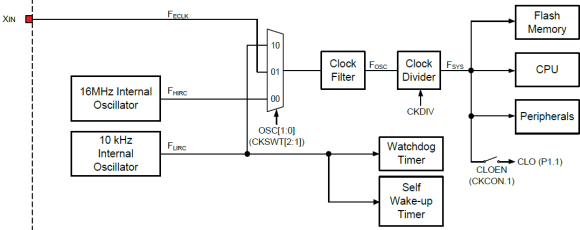
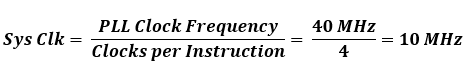
In the demo, I used external interrupt channel EXTI0 and Timer 0. The system clock frequency is set to 16MHz with HIRC. Timer 0 is set in Mode 1 and its counter is rest to 0 count. EXTI0 is set to detect falling edges. Note that the timer is set but not started.
TIMER0_MODE1_ENABLE;
set_Timer_0(0x0000);
set_IT0;
set_EX0;
set_EA;
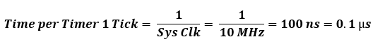
Also note that each tick of Timer 0 here is about:
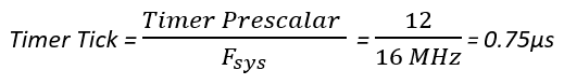
Based on this tick info, we can deduce the maximum and minimum pulse durations as like:
#define sync_high 22000 // 22000 × 0.75ms = 16.5ms
#define sync_low 14000 // 14000 × 0.75ms = 10.5ms
#define one_high 3600 // 3600 × 0.75ms = 2.7ms
#define one_low 2400 // 2400 × 0.75ms = 1.8ms
#define zero_high 1800 // 1800 × 0.75ms = 1.35ms
#define zero_low 1200 // 1200 × 0.75ms = 0.9ms
Now when an IR transmission is received, an interrupt will be triggered. Therefore, in the ISR, we immediately capture the timer’s tick count and reset it. When all 33 pulses have been received this way, we temporarily halt all interrupts by disabling the global interrupt and stop the timer in order to decode the received signal. P15 is also toggled to demonstrate reception.
void EXTI0_ISR(void)
interrupt 0
{
frames[bits] = get_Timer_0();
bits++;
set_TR0;
if(bits >= 33)
{
received = 1;
clr_EA;
clr_TR0;
}
set_Timer_0(0x0000);
P15 = ~P15;
}
Now the signal is decoded in the decode function. This function scans a fixed length of time frames for sync, ones and zeros and return the value obtained by scanning the time info of the pulses. In this way, a received signal is decoded.
unsigned char decode(unsigned char start_pos, unsigned char end_pos)
{
unsigned char value = 0;
for(bits = start_pos; bits <= end_pos; bits++)
{
value <<= 1;
if((frames[bits] >= one_low) && (frames[bits] <= one_high))
{
value |= 1;
}
else if((frames[bits] >= zero_low) && (frames[bits] <= zero_high))
{
value |= 0;
}
else if((frames[bits] >= sync_low) && (frames[bits] <= sync_high))
{
return 0xFF;
}
}
return value;
}
In the main loop, the decode info are displayed on a text LCD.
Demo
Epilogue
After going through all these topics and exploring the N76E003 to the finest details, I have to say that just like flagship killer cell phones, this is a flagship killer 8-bit microcontroller. In terms of price vs feature ratio, it is a winner. I’m truly impressed by its performance and hardware features. It offers something like an 8051 but with more advanced modern features. Old-school 8051 users will surely love to play with it.
Every day we talk about software piracy and hacking but little effort is done to prevent them. Students, hobbyists and low-profile business houses can’t afford to use the expensive Keil/IAR compiler. They often go for pirated versions of these software and this is a very wrong path to follow. Like I said in my first post on N76E003, Nuvoton has rooms for making its devices more popular by investing on a compiler of its own or at least start doing something with free Eclipse-IDE.
PDF version of this post can be found here.
All files and code examples related to Keil compiler can be downloaded from here.
All files and code examples related to IAR compiler can be downloaded from here.
Happy coding.
Author: Shawon M. Shahryiar
https://www.youtube.com/user/sshahryiar
https://www.facebook.com/groups/microarena
https://www.facebook.com/MicroArena
06.08.2018
The post Getting Started with Nuvoton 8-bit Microcontrollers – Coding Part 3 appeared first on Embedded Lab.